17
EN1R--9161 0006R10--NE
If no air is proven by the air proving switch, the ignition control
stays waiting (optional lock out on no air can be included).
Suffix DD and TD (see fig. 33.)
As CD and RD except flame relay contact or opto is activated
after flame detection.
Suffix SD (see fig. 27.)
If line voltage is applied between pin 5 (line valves) and
pin 9 (N), the gas valve is switched on.
If the line voltage is applied between pin 4 (line ignition) and
pin 9 (N) the build in igniter is switched on.
The igniter circuit is fed during the negative half wave of the
mains.
Pin 8 is present but not intended for use. It is connected with a
resistor (100 τ)topin5.
Ignition circuit must be on shorter than 10 s in an application
with single ignition trial.
Gas/air app lication
For gas/air application without dynamic aircheck, the
S4565AD, BD, PD or QD c an be used.
In this application the fan is connected between pin 4 and 5
and will start when a call for heat is present. The waiting
period now acts as a prepurge time.
When the call for heat disappears or when the ignition control
goes in lock --out, the fan will be switched off.
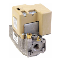
T
c+
T
w
T
s
Thermostat
Alarm
Ignition
Gas valve
Flame rod
Legend
T
c+
T
w
T
FR
Fig. 30. Functional diagram S4565AD, PD “2000”series
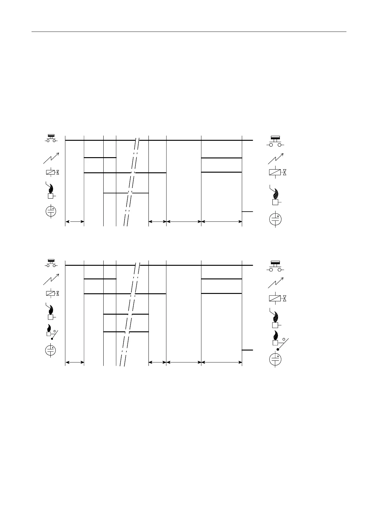
T
s
Thermostat
Alarm
Ignition
Gas valve
Flame rod
Legend
Flame relay contact
T
c+
T
w
T
c+
T
w
T
FR
Fig. 31. Functional diagram S4565BD, QD “2000”series
 Loading...