18
EN1R--9161 0006R10--NE
P
P
Thermostat
Fan
Air proving switch
Ignition
Gas valve
Flame rod
Legend
T
s
Alarm
T
c+
T
w
T
c+
T
w
T
FR
Fig. 32. Functional diagram S4565CD, RD “2000”series
P
P
Thermostat
Fan
Air proving switch
Ignition
Gas valve
Flame rod
Legend
T
s
Flame relay contact
Alarm
T
c+
T
w
T
c+
T
w
T
FR
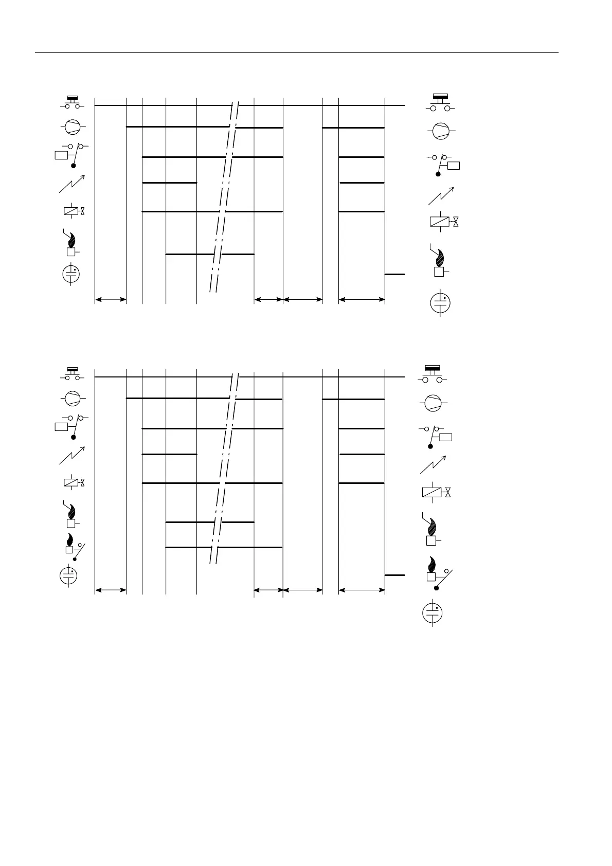
Fig. 33. Functional diagram S4565DD, TD “2000”series
SPECIFICATIONS IGNITION CONTROL S4565AF, BF, CF, DF, PF, QF, RF, TF
Model
Suffix AF: atmospheric, direct burner ignition
Suffix BF: atmospheric, intermittent pilot burner ignition
including safety timer
Suffix CF: fan assisted, direct burner ignition
Suffix DF: fan assisted, intermittent pilot burner ignition
including safety timer
Suffix PF: as AF except volatile lock--out
Suffix QF: as BF except volatile lock--out
Suffix RF: as CF except volatile lock--out
Suffix TF: as DF except volatile lock--out
Supply voltage
220 ... 240 Vac, 50/60 Hz
Power consumption
4VA
 Loading...