19
EN1R--9161 0006R10--NE
Humidity
90% RH max. at 40 _C
Ambient temperature
0 ... 60 _C
--15 ... 60 _C (optional)
Electrical rating (see also n ote 12.)
Alarm: 220 ... 240 Vac, 50/60 Hz, 1 A, cos ♥ >0.6or
max 1mA
Fan: 220 ... 240 Vac, 50/60 Hz, 1 A, cos ♥ >0.6
LPG outdoor valve: 220 ... 240 Vac, 50/60 Hz, 1 A,
cos ♥ >0.6
Electrical connection
High voltage spark: 2.8 mm spade terminal
Optional: 4 mm round terminal
Flame sensing:4.8 mm spade terminal or 2.8 mm spade
terminal for combined high voltage
spark/flame sensing
PCB connectors:Molex 3003 series suitable for Molex 3001
female cable connector
Housing (degree of protection)
See page 29
Timing (depending on O.S. number)
Self check time (T
c
): 1.5 s
Waiting time (T
w
): 0 ... 30 s
Safety time (T
s
): 3.5 ... 55 s
Extended spark ignition time and stabilisation time: 0 ... T
s
(dependent on elaps of safety time)
External main burner interrupt
Max open contact voltage 24 V, max current 15 mA
A low voltage relay is suitable.
An opto coupler e.g. CNY17--3 is also possible
A flame indicating series LED (see connection diagram) will
conduct min 0.85 mA if the contact is open and minimal
3.5 mA if the contact is closed.
Flame sensing
Min flame c u rrent: 0.9 ←A
Response time on: > 0.2 s
Response time off (T
FR
):<1s
Ignition
Spark voltage: > 12 kV at 40 pF load
Repetition rate: 2.5 ... 60 Hz (depending on O.S. number)
Max spark gap: 3.5 mm
Leng th flame sensing cable
1mmax.
Length ignition cable
0.5 m max.
Length of wiring for external components
1mmax.
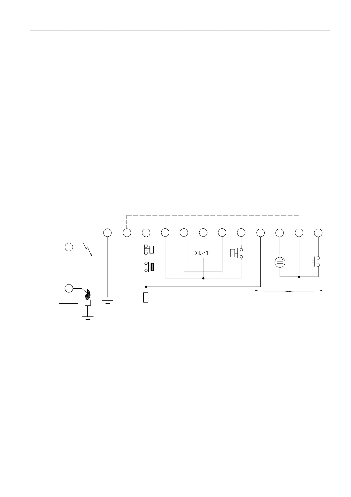
Side connections**
10
3
7
1
L
11
N
8
24
569
LPG
LM
G
RS
12
*
P -- Air proving switch
LM -- Limiter
RS -- Reset switch
* See note 12.
** Alternative side connection for models with combined flame
detection/high voltage. See page 5 fig. 6.
Optional
Fig. 34. Connection diagram S4565AF, BF, PF, QF
 Loading...