26
EN1R--9161 0006R10--NE
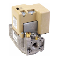
SPECIFICATIONS INTERMITTENT PILOT IGNITION CONTROL S4585D
Model
Suffix D: fan assisted, intermittent pilot burner ignition
Supply voltage
220 ... 240 Vac, 50/60 Hz
Power consumption
4VA
Humidity
90% RH max. at 40 _C non condensing
Ambient temperature
0 ... 60 _C
Electrical rating
Fan: 220 ... 240 Vac, 50/60 Hz, 1 A, cos ♥ >0.6
No flame indicator: 220 ... 240 V, 1 mA max
Electrical connection
High voltage spark/flame sensing single rod:
2.8 x 0.5 mm s pade terminal
PCB connectors:
Molex 3003 series suitable for Molex 3001 female
cable connector
Housing (degree of protection)
See page 29
Timing (depending of O.S. number)
Self check time (T
c
): 1.5 s
Safety time (T
s
): infinite
Flame sensing
Min flame c u rrent: 1.0 ←A
Response time on: > 0.2 s
Response time off (T
FR
): < 1.0 s
Phase--Phase mains trafo input: 220 ... 240 > 0.1 VA
Ignition
Spark voltage: > 12 kV at 40 pF load
Repetition rate: 1 ... 4 Hz
Max spark gap: 3.5 mm
Length ignition and flame sensing cable
0.5 m max.
Length of wiring for external components
1mmax.
Recommend ed flame sensor
Q371/Q385 ”2000 series”/Q389/Q395 intermittent ignition pilot
burner
Maximum pilot burner output
250 Watt
No flame ind icator
Required impedance: > 100 kτ
No flame ind ication time
T
NF
:>10s
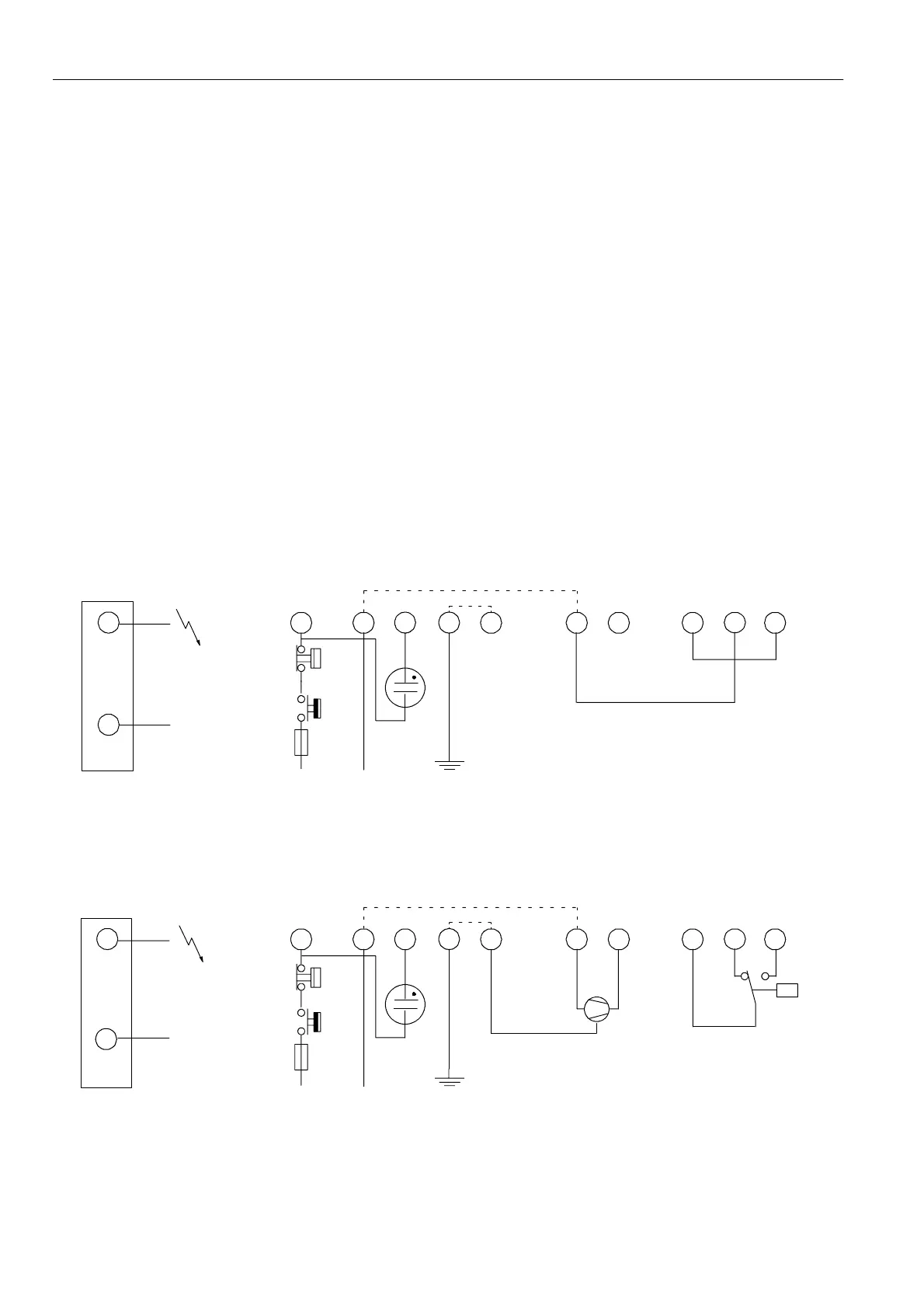
12 11 9 8 6
1
23
L
5
N
Side connections
LM
10
NF
Optional
LM -- Limiter
NF -- No flame indicator
** Alternative side connection for models with combined flame
detection/high voltage. See page 5 fig. 6.
Fig. 45. Connection diagram S4585D wired up in atmospheric application
P
12
11
9
86 1
2
3
L
5
¯
N
Side connections
¯
LM
10
NF
Optional
LM -- Limiter
P -- Air proving switch
NF -- No flame indicator
** Alternative side connection for models with combined
flame detection/high voltage. See page 5 fig. 6.
Fig. 46. Connection diagram S4585D wired up in fan assisted application
 Loading...