25
EN1R--9161 0006R10--NE
SYSTEM OPERATION
General
The S4575A, B, P, Q ignition controls can provide hot surface
ignition.
The Hot Surface Igniter (HSI is connected to a floating
winding of a transformer (see fig 41., 42.).
Lock- out reset
The S4575 can be is reset by either depressing the
internal/external reset button (suffix A and B) or by interrupting
the permanent life (suffix P and Q).
NOTE 14.: If during normal use the reset button is pressed,
the gas valves close and the S4575 ignition
control starts a new sequence after releasing the
reset button.
NOTE 15.: If permanent alarm output: neon indicator with
integral resistor >150 kτΕmax 1 mA)
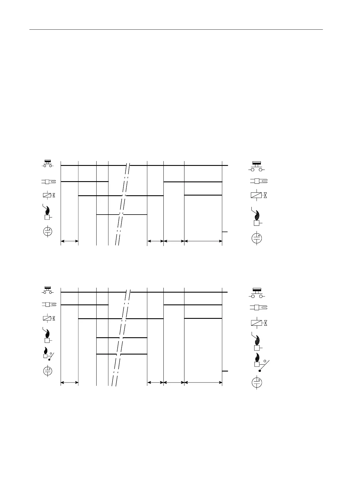
Suffix A and P (see fig. 43.)
When there is a call for heat the HSI starts glowing during
glowing time (T
g
).
Afte r the glowing time (T
g
) the gas valve is switched on.
The igniter ignites gas and resulting flame is detected by the
flame rod.
After flame establishment a predetermined, extended ignition
time can be included.
If flame is not established within the safety time (T
s
), the
S4575 ignition control locks out.
If the flame is lost during normal run, the S4575 ignition
control repeats start sequence.
Suffix B and Q (see fig. 44.)
As suffix A and suffix P except flame relay contact is closed
after flame detection.
T
g
T
s
Thermostat
Alarm
Ignition
Gas valve
Flame rod
Legend
T
g
T
FR
Fig. 43. Functional diagram S4575A, P
T
s
Thermostat
Alarm
Ignition
Gas valve
Flame rod
Legend
Flame relay contact
T
g
T
g
T
FR
Fig. 44. Functional diagram S4575B, Q
 Loading...