7
EN1R--9161 0006R10--NE
T
c+
T
p
P
P
¯
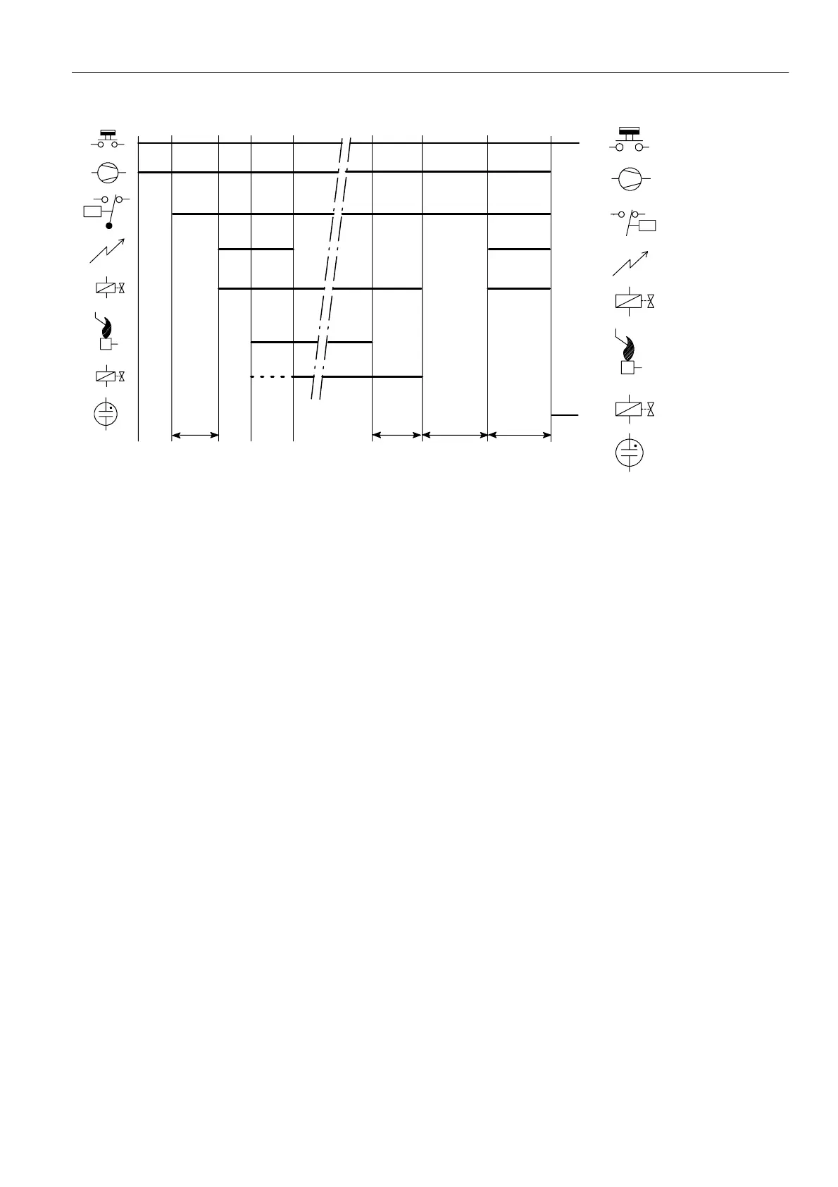
Thermostat
Fan
Air proving switc
Ignition
Pilot valve
Flame rod
Legend
T
s
PV
MV
Main valve
PV
MV
Alarm
T
c+
T
p
T
FR
Fig. 9. Functional diagram S4565D, T
SPECIFICATIONS DIRECT BURNER IGNITION CONTROL
S4565AD, BD, CD, DD, PD, QD, RD, TD “1000- SERIES”
Model
Suffix AD: atmospheric, direct burner ignition
Suffix BD: as AD but with flame relay output
Suffix CD: fan assisted, direct burner ignition
Suffix DD: as CD but with flame relay output
Suffix PD: as AD except volatile lock--out
Suffix QD: as BD except volatile lock--out
Suffix RD: as CD except volatile lock --out
Suffix TD: as DD except volatile lock--out
Supply voltage
220 ... 240 Vac, 50/60 Hz
Power consumption
4VA
Humidity
90% RH max. at 40 _C non condensing
Ambient temperature
0 ... 60 _C
--15 ... 60 _C (optional)
Electrical rating (see also n ote 8.)
Alarm: 220 ... 240 Vac, 50/60 Hz, 1 A, cos ♥ > 0.6 or max 1mA
Fan: 220 ... 240 Vac, 50/60 Hz, 1 A, cos ♥ >0.6
Flame relay contact: 220 ... 240 Vac, 50/60 Hz, 1 A,
cos ♥ >0.6
Flame opto coupler: +5 V, 10 kτ
LPG valve: 220 ... 240 Vac, 50/60 Hz,1 A max, cos ♥ >0.6
Electrical connection
High voltage spark: 2.8 x 0.5 mm spade terminal
Flame sensing: 4.8 x 0.8 mm spade terminal
PCB connectors: Molex 3003 series suitable for Molex 3001
female cable connector
Housing (degree of protection)
See page 29
Timing (depending on O.S. number)
Self check time (T
c
): 1.5 s
Waiting time (T
w
): 0 ... 30 s
Safety time (T
s
): 3.5 ... 25 s
Extended spark ignition time: 0 ... T
s
(dependent on elaps of safety time)
Flame sensing
Min flame c u rrent: 0.9 ←A
Response time on: > 0.2 s
Response time off (T
FR
): < 1 s
Ignition
Spark voltage: >12 kV at 40 pF load
(depending on O.S. number)
Repetition rate: 2.5 ... 60 Hz (depending on O.S. number)
Max. spark gap: 3.5 mm
Optional external ignition circ uit: 220 ... 240 V (at no load),
single phase rectified, max 2 VA
Leng th flame sensing cable
1mmax.
Length ignition cable
0.5 m max.
Length of wiring for external components
1mmax.
 Loading...