23
EN1R--9161 0006R10--NE
P
P
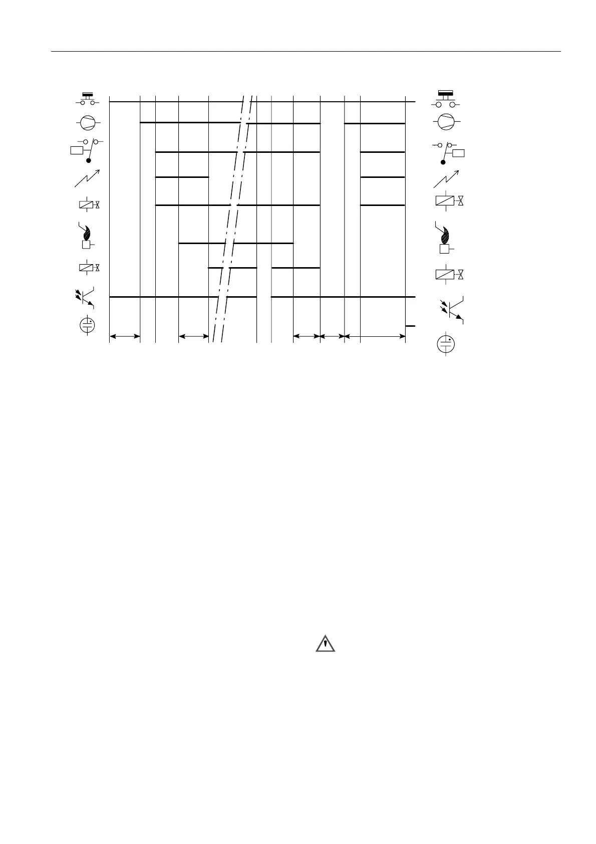
Thermostat
Fan
Air proving switch
Ignition
Pilot valve
Flame rod
Legend
T
s
PV
MV
Main valve
PV
MV
Alarm
T
c+
T
w
T
c+
T
w
T
FR
MBI
Main burner interrupt
T
ext
MBI
Fig. 40. Functional diagram S4565DF, TF
SPECIFICATIONS DIRECT BURNER IGNITION CONTROL S4575A, B, P, Q
Model
Suffix A: atmospheric, direct burner ignition
Suffix B: as A but with flame relay output
Suffix P: as A except volatile lock--out
Suffix Q: as B except volatile lock--out
Supply voltage
230 ... 240 Vac, 50/60 Hz (--15%, +10%)
Power consumption
4VA
Humidity
90% RH max. at 40 _C
Ambient temperature
0 ... 60 _C
--15 ... 60 _C (optional)
Electrical rating
Alarm: 230 ... 240 Vac, 50/60 Hz, max 1 mA
Fan: 230 ... 240 Vac, 50/60 Hz, 1 A, cos ♥ >0.6
Flame relay contact: 230 ... 240 Vac, 50/60 Hz, 1 A,
cos ♥ >0.6
Flame opto coupler: +5 V, 10 kτ
Electrical connection
Hot surface ignition relay: 2.8 mm spade terminal
Flame sensing: 4.8 mm spade terminal
PCB connectors: Molex 3003 series suitable for Molex 3001
female cable connector
Housing (degree of protection)
See page 29
Timing (depending on O.S. number)
Self check time (T
c
): 1.5 s
Glowing time (T
g
): 0 ... 30 s
Safety time (T
s
): 3.5 ... 25 s
Extended ignition time: 0 ... T
s
(dependent on elaps of safety time)
Flame sensing
Min flame c u rrent:
for optional phase independent versions: 0.5 ←A
for phase dependent versions: 0.9 ←A
Response time on: > 0.2 s
Response time off (T
FR
): < 1 s
Hot surface ignition relay
Free contact: 230 ... 240 Vac, 2 A, cos ♥ =1
24 Vac, 2 A, cos ♥ =1
120 Vac, 2 A, cos ♥ =1
WARNING
Hot Surface Igniter (HSI) needs to be supplied from a
floating winding of a transformer in order to quarantee
reliable flame detection.
Leng th flame sensing cable
1mmax.
 Loading...