24
EN1R--9161 0006R10--NE
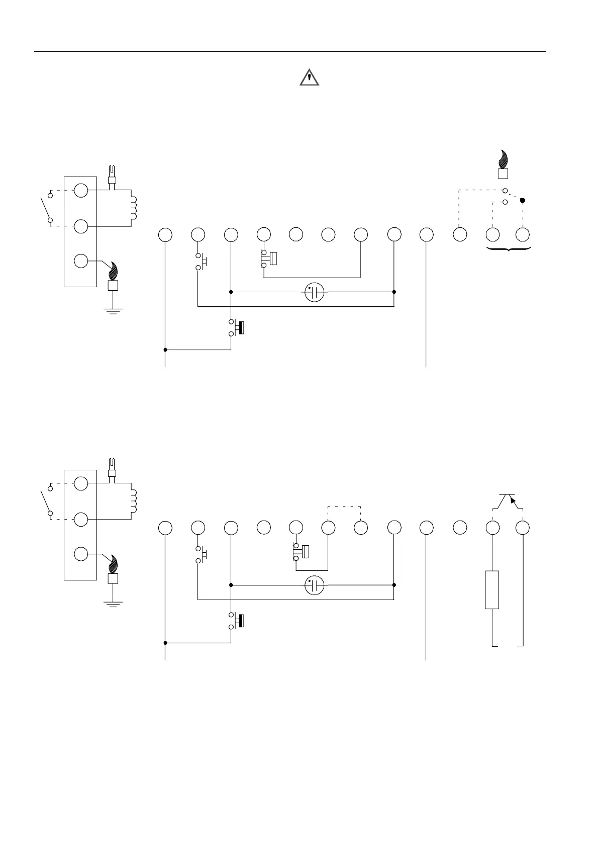
Length of wiring for external components
1mmax.
Remark
Optional integrated flame relay available with safe separation
or opto coupler with safe separation.
N.C. contact of flame relay has no safe separation.
WARNING
Opto coupler interface needs a debounce
time > 20 ms in order to prevent noise caused by
transients on mains.
9
8
65
L
10
12
712
LM
3
411
Side connections
RS
N
OptionalOptional
24 ... 240 V
LM -- Limiter
RS -- Reset s witch
* See page 10 fig. 17.
Reset switch and alarm
are optional
*
Fig. 41. Connection diagram S4575A, B, P and Q
9
8
65
L
10
12
712
LM
3
411
Side connections
LM -- Limiter
RS -- Reset s witch
RS
N
Optional
24 ... 240 V
10k
5V
+--
Fig. 42. Connection diagram S4575B 1009
 Loading...