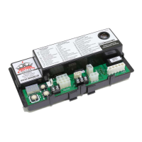
S9361A207X INTEGRATED BOILER CONTROLLERS
69-2751—05 6
WIRING
Electrical Shock Hazard.
Can cause severe injury, death or property
damage.
Disconnect the power supply before making
wiring connections to prevent electrical shock
or equipment damage.
Check the wiring diagram furnished by the appliance
manufacturer for circuits differing from the wiring
hookup shown in Fig. 4. Carefully follow any special
instructions affecting the general procedures outlined
below.
IMPORTANT
1. All wiring must comply with applicable local
electrical codes and ordinances.
2. A common ground is required for the S93XX
and the main burner. The 24V “secondary”
plug internally grounds one side of the trans-
former. Any auxiliary controls or limits must
not be in the grounded leg. In addition, the
appliance should be earth-grounded.
3. Make sure the transformer has adequate VA.
The ignition module requires at least 0.2A at
24 Vac. Add the current draws of all other
devices in the control circuit, including the gas
control, and multiply by 24 to determine the
total VA requirements of these components.
Add this total to 5.0 VA (for the module). The
result is the minimum transformer VA rating.
Use a Class II transformer if replacement is
required.
4. Check that L1 (hot) and L2 (neutral) are wired
to the proper terminals.
Connect Ignition Cable (S936XAXXXX)
Use Honeywell ignition cable or construct an ignition
cable that conforms to suitable national standards,
such as Underwriters Laboratories Inc. See
Specifications section. To construct a cable, fit one
end (the module end) with 1/4 in. connector
receptacle and the other with a connector to match
the pilot assembly. Protect both ends with insulated
boots.
NOTE: Cable length must be 36 in. (0.9 m) or less.
The cable must not be in continuous contact
with a metal surface or spark voltage will be
greatly reduced. Use ceramic or plastic
standoff insulators as required.
1. Connect one end of the cable to the male
quick-connect SPARK terminal on the module.
2. Connect the other end of the cable to the igniter
or igniter-sensor stud on the pilot
burner/igniter-sensor.
Connect Vent Damper (Vent Damper
Models)
A vent damper can be used with modules provided
with a vent damper plug connector. The Molex
®
plug
provided simplifies wiring connections.
To connect the vent damper, follow the wiring
diagrams supplied with the vent damper for typical
connections.
Connect Remaining Module
Connectors
Connect remaining system components to the
ignition module terminals as shown in the appropriate
wiring diagrams, Fig. 4.
Connect Gas Control
Use No. 18 AWG or larger, depending on estimated
curret draw, solid or stranded wire. Connect to gas
control terminals as shown in wiring diagrams, using
terminals appropriate to the gas control.
Ground Control System
The igniter/flame sensor and module must share a
common ground with the main burner. Use AWM
insulated wire with a minimum rating of 105°C
(221°F) for the ground wire; asbestos insulation is not
acceptable. If necessary, use a shield to protect the
wire from radiant heat generated by the burner.
The burner serves as the common grounding area. If
there is not a good metal-to-metal contact between
the burner and ground, run a lead from the burner to
ground.
NOTE: “Earth” ground is not required.
Transformer: Add current ratings of module, gas
control, vent damper and any other components of the
control system to determine transformer size
requirements.
Table 4. Specific Ignition Timings.
a
Ignition Activation Period is the time that the hot surface igniter remains powered after the gas valve opens.
b
Purge Timing specified in seconds.
Model
Ignition
Type Draft Type
No. of
Ignition
Trials
Igniter/S
ensor
Type
Automati
c Restart
Time
Ignition
Activatio
n Period
a
Prepurg
e
Timing
b
Postpurg
e Timing
b
S9360A Intermittent
Pilot - Spark
Induced Infinite Combined 1 hour N/A 30 0
S9360A Intermittent
Pilot - Spark
Atmospheri
c
Infinite Combined 1 hour N/A 2.75 0
 Loading...