Planning Protections
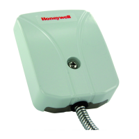
Figure 5-2 Layout Plan
Wall
Wall
Wall WallFloor
Ceiling
7
meter
3
meter
5
meter
Layout Plan for a Vault 7x5x3 meters
Planning Guidelines
The detection range will be reduced if joints or cracks exist in the vault, corners, between
walls and floor, and/or on the ceiling. In these cases apply detectors on both sides of
irregularity found.
The vault door can be protected by direct mounting a detector inside the door leaf or
outside the door. Here the Movable Mounting Kit SC111 or the Keyhole Protection Kit
SC112 can be used.
A detector can preferably be mounted on the door frame to protect the walls on either side
of the door and partly the vault door when installing the detectors in an existing vault.
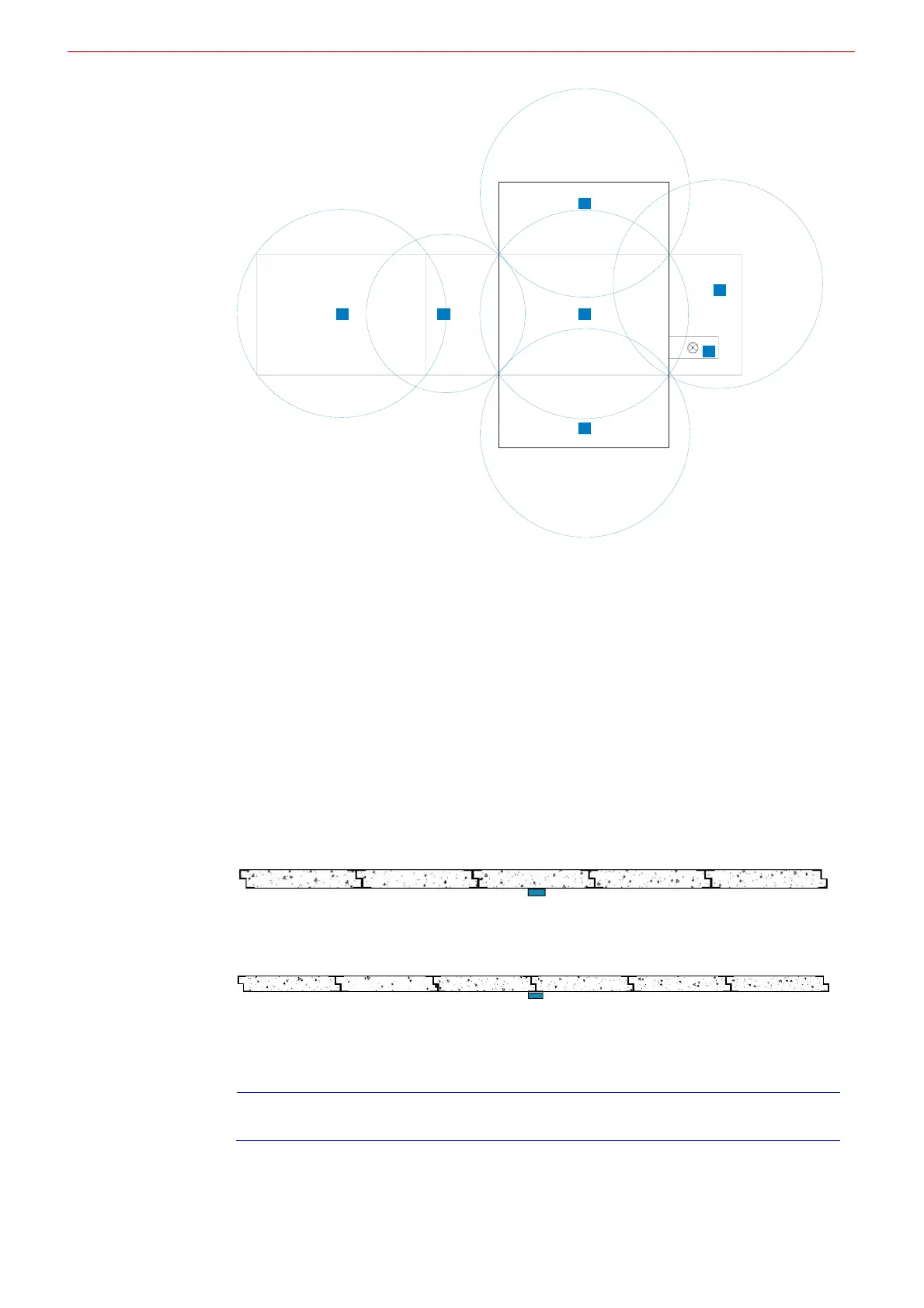
Module Vaults must be bolted and welded together to get a reasonable detection range.
One maximum module (width is 1000mm and length is 6500mm) can be covered on the
other side of a welded corner.
Detector mounted on the centre of one module can cover 5 adjacent modules at most.
Figure 5-3 Detector mounted on the center of one modular vault
Detector mounted on welded mounting plate between two modules can cover 6 adjacent
modules at most.
Figure 5-4 Detector mounted between two modular vaults
Before reducing the sensitivity where noise level is high, the noise source should be
removed firstly.
Drill tests should be performed on the outside of the vault.
Note
This guideline is typical recommendation for detector mounting and has always to be
followed up by practical sensitivity and noise check before the installation is taken in use.
- 8 -
 Loading...