23
MAN0530 Issue 09 October 03 Searchline Excel
2104M0506
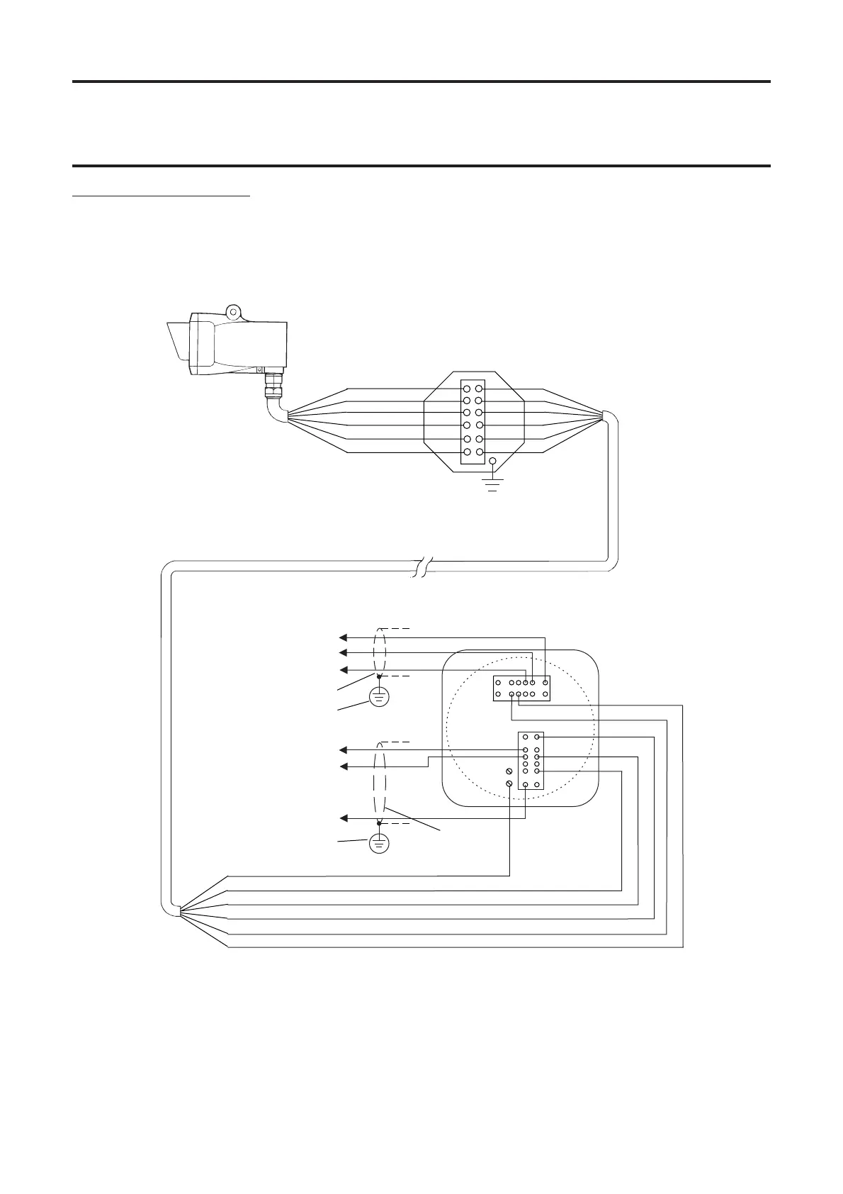
3. INSTALLATION AND OPERATION
Wiring with DX100 (M)
See also DX100 Termination Units Technical Handbook.
Blue B
Orange A
Black 0V
White 4-20
Red +24V
Green/ GND
Yellow
Orange A
Green/Yellow GND
Black 0V
White 4-20
Red +24V
Blue B
Control cabinet
connections
Receiver
Local junction box
(mounted on Receiver mounting plate)
DX100 (M) junction box
(mounted in a convenient and
accessible position)
Modbus A
Modbus B
Screen - Modbus Drain
+24VDC in
4-20mA - out
0VDC - in
Cable shield
Instrument (clean)
earth
TB2
TB1
1
Instrument (clean)
earth
Cable shield
Safety/protective ground
The earth bonding arrangement must ensure that the maximum peak
voltage between the unit case earth and any field cable conductor is less
than 350V. Voltages in excess of this can cause permanent damage to the
unit’s RFI protection filters.
 Loading...