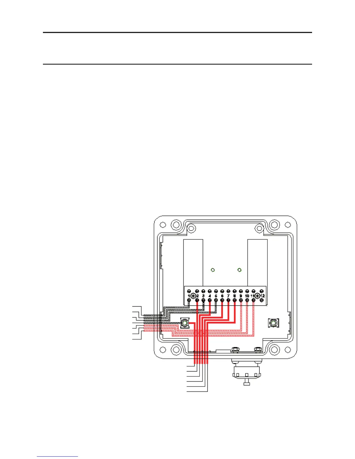
+24VDC IN (Terminal 1)
0V (Terminal 3)
4-20mA (Terminal 5)
Earth Te rminal
MOD BUS Drain (Terminal 9)
MOD BUS A (Terminal 10)
MOD BUS B (Terminal 11)
Field Wiring
Excel Receiver
Wiring
Earth Te rminal
+24VDC (Red) (Terminal 2)
0V (Black) (Terminal 4)
4-20mA (White) (Terminal 6)
RS485 (A) (Orange) (Terminal 7)
RS485 (B) (Blue) (Terminal 8)
3. INSTALLATION AND OPERATION
k. All electrical equipment connected to the gas detector should comply with EN61000-6-
3:2007 and EN61000-6-2:2005.
l. The24Vsupplyshouldbefreefromlargetransientsanductuations.
m. Theeldcablingconductorsshouldhavesufcientcrosssectionalareatoensurethat
the minimum supply voltage applied to the gas detector is 18V at a current of 420mA.
This corresponds to a maximum round loop impedance of 14 ohms for a nominal 24V
system supply.
n. Receivers should not be installed in close proximity to the antennae of high powered
radio, radar and satellite communication equipment.
The following diagrams show typical earth bonding arrangements for various installations.
3.3.2 Receiver Connections via DVC100(M) MK2
The earth bonding arrangement must ensure
that the maximum peak voltage between the unit
caseearthandanyeldcableconductorisless
than 350V. Voltages in excess of this can cause
permanent damage to the unit's RFI protection
lters.
Note: Using metal cable glands will connect the screen of the cable to the Excel Body.

 Loading...