22
MAN0530 Issue 10 - 11/09 Searchline Excel
2104M0506
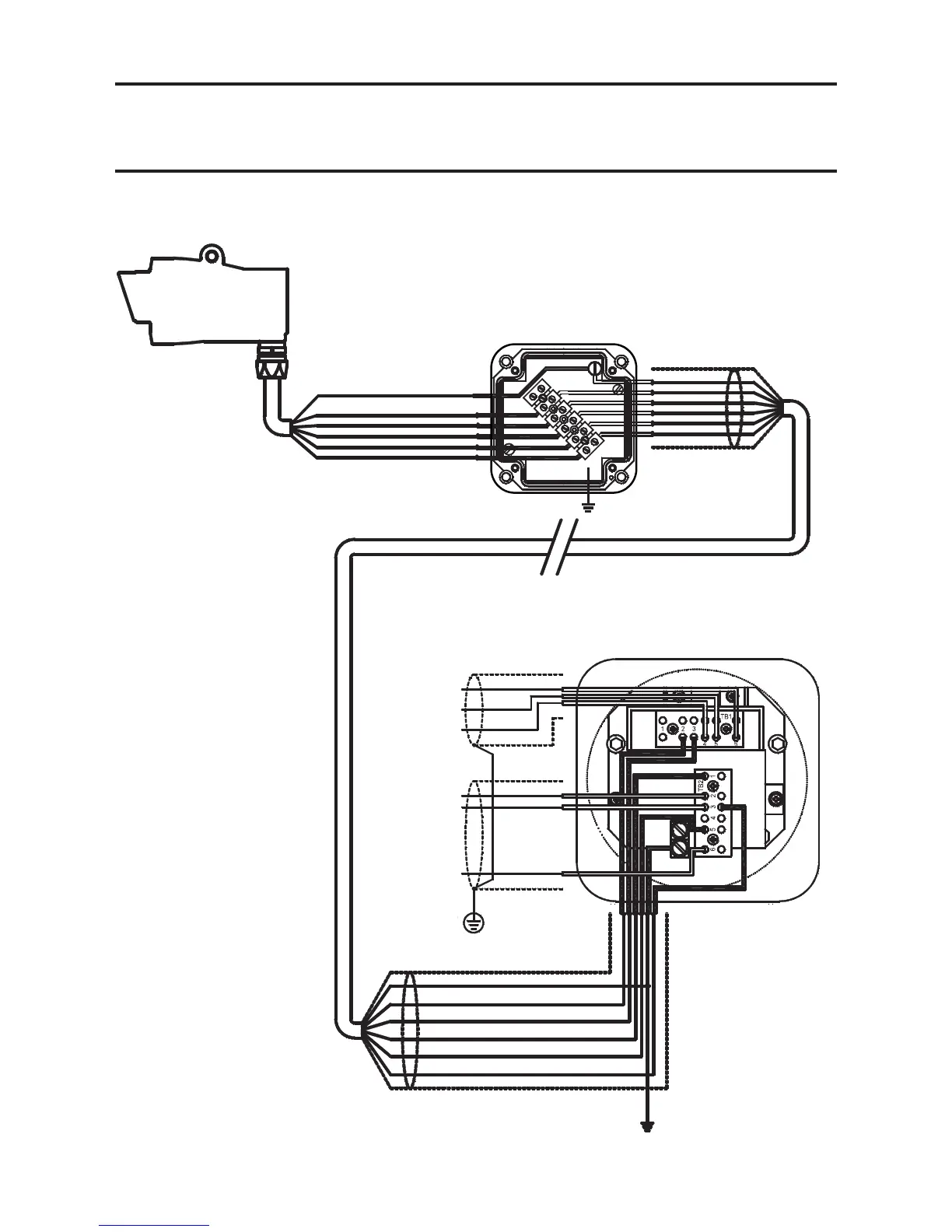
3. INSTALLATION AND OPERATION
Wiring with DX100(M)
See also DX100 Termination Unit's technical Handbook.
EXCEL
RECEI VER
ORANGE (A) TB1/2
RED (+24V) TB2/1
BLACK (0V) TB2/5
WHITE (4-20mA) TB2/3
DX100(M) JUNCTION BOX
(mounted in a convenient and accessible position)
CABLE SCREEN
SAFETY / PROTECTIVE
GROUND
Where the DX100(M) is not bonded
to a local safety/ protective earth
then an external safety / protective
earth needs to be made as shown.
LOCAL JUNCTION BOX
(mounted on Receiver mounting plate)
WHITE (4-20mA)
BLACK (0V)
RED +24V
BLUE (B)
ORANGE (A)
GREEN/YELLOW (EARTH)
Same potential as Excel body and conduit
Use isolating glands where necessary
EXCEL
RECEIVER
DX100(M) JUNCTION BOX
(mounted in a convenient and accessible position)
CABLE SCREEN
GREEN/YELLOW (EARTH)
BLUE (B) TB1/3
RED (+24V) TB2/1
BLACK (0V) TB2/5
WHITE (4-20mA) TB2/3
SAFETY/PROTECTIVE GROUND
Where the DX 100(M) is not bonded
to a local safety/protective earth then
an external safety/protective earth
needs to be made as shown.
CABLE SCREEN
CONTROL
CABINET
CONNECTIONS
4-20mA OUT (TB2/3)
0V (TB2/6)
+24V (TB2/2)
CABLE SCREEN
INSTRUMENT (CLEAN)
EARTH STAR-POINT
Modbus A (TB1/6)
Modbus B (TB1/5)
Modbus Drain
CABLE SCREEN
CONTROL
CABINET
CONNECTIONS
CABLE SCREEN
CABLE SCREEN
INSTRUMENT (CLEAN)
EARTH STAR-POINT
Modbus B (TB1/5)
Modbus A (TB1/6)
Modbus Drain
+24V (TB2/2)
4-20mA OUT (TB2/3)
0V (TB2/6)
The earth bonding arrangement
must ensure that the maximum
peak voltage between the unit
caseearthandanyeldcable
conductor is less than 350V.
Voltages in excess of this can
cause permanent damage to the
unit'sRFIprotectionlters.

 Loading...