6.3 Terminal connections
All electrical connections are made at the terminal module. To access the terminal module follow the
procedure below:
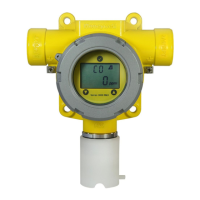
1. Remove the detector’s cover by unscrewing it in a counter-clockwise direction.
2. Remove the display module by pulling it rmly away from the enclosure without twisting it.
6.4 Cable and earth / ground connection
Between the Controller and Transmitter use 2 core (plus screen 90% coverage), suitably mechanically
protected copper cable with a suitable M20 explosion-proof gland, or ¾ in. NPT steel conduit, with 0.5
to 2.0mm2 (equivalent approx. 20 to 14AWG) conductors. Ensure the cable gland is installed correctly
and fully tightened.
To ensure good EMC/RFI immunity bond the system to ground / earth as shown in the diagram below.
Notes:
• No two ‘Earth Points’ should be connected via screen and / or conduit so as to avoid ‘ground loops’.
(Except between the sensor and transmitter which is a digital link).
• Where multiple ‘Earth Points’ are unavoidable (e.g. transmitter mounted on metal superstructure
which is earthed then screen and / or conduit to controller should be isolated appropriately).
• ‘ Bonded Points’ (continuity of screen) may be achieved using appropriate glands / cable or conduit;
internal and external ‘Earth Points’ in the transmitter are provided.
Internal Earth/
Ground Connection
Conduit/Cable Entry
Display Module
Plug in Socket
Supplementary
External Earth/
Ground Connection
Note: Nominal tightening
torque of 6.9lb-in. to be
applied to the terminal
clamping screws.
Terminal
number
Detector
Terminal
Controller
Connection
1 + +VE
2 - Signal
 Loading...