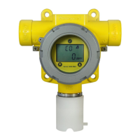
9. Display and user interface
The display module comprises of an LCD and 3 magnetic user interface switches. The three switches (‘▲’
UP, ‘▼’ DOWN and ‘’ MENU / ENTER) are located above and below the LCD display as shown below:
Diagram 11: Display and User Interface
Magnetic DOWN switch (▼)
The DOWN switch is used to scroll through status or menu items or to decrease a value.
Magnetic UP switch (▲)
The UP switch is used to scroll through status or menu items or to increase a value.
Magnetic MENU / ENTER switch ()
The MENU / ENTER switch is used to enter the Review and Menu modes, to enter a selected value
and to clear a Warning / Fault that has been rectied.
Gas Type
Series 3000 MkII can be tted with different sensors to measure 15 different gases. So the user can
identify which gas the detector is measuring, it shows the gas formula of the sensor tted on the display.
See diagram 12 for a list of the different gases and their corresponding gas formula displays.
Gas Reading
The gas reading displays the current measured gas concentration.
Measuring units (%Vol/ppm)
The toxic gas measurement units are in parts per million (ppm) and the oxygen gas measurements
units are in percent by volume (%Vol).
Calibration icon
When performing a zero calibration, the zero calibration icon ( ) is displayed. When performing a span
calibration the span calibration icon ( ) is displayed.
Magnetic
MENU/ENTER
Switch
Calibration Icon
Gas Type
Test Pass Icon
Gas Reading
Warning/Fault Icon
Magnetic
DOWN Switch
Inhibit Icon
Measuring Units
Magnetic
UP Switch
 Loading...