EasyManua.ls Logo

Honeywell T7300D

Honeywell T7300D
40 pages
To Next Page IconTo Next Page
Loading...
PRODUCT DATA
LonWorks® is a registered trademark of Echelon Corporation.
® U.S. Registered Trademark
Copyright © 1999 Honeywell Inc. • • All Rights Reserved
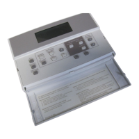
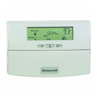
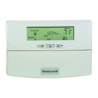
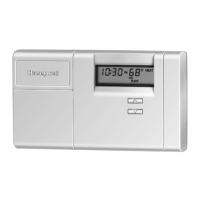
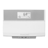
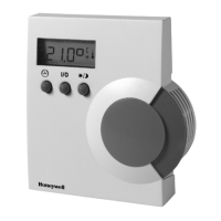
T7200D,E, T7300D,E,F and Q7300
Series 2000 Programmable Commercial
Thermostats and Subbases
APPLICATION
The T7200, T7300 Thermostats and Q7300 Subbases control
24 Vac commercial single zone heating, ventilating and air
conditioning (HVAC) equipment. In addition, the Q7300H
Communicating Subbase can communicate schedule
information and system instructions to other devices in a
LonWorks® network.
FEATURES
All Models:
7-day programming.
Two Occupied and two Unoccupied periods per day.
Individual heat and cool setpoints available for
Occupied and Unoccupied periods.
Proportional plus Integral (P+I) control eliminates
temperature fluctuations.
Intelligent Recovery® control automatically optimizes
equipment start times based on building load.
Intelligent Fan™ feature energizes fan continuously in
the Occupied periods. Fan can also be configured for
conventional heat or electric heat fan operation.
Automatic or manual changeover models available.
Universal Versaguard™ Thermostat guards available.
Convenient overrides allow temporary setpoint changes.
Keypad lockout available.
T7200D,E Thermostats
Use on single-stage conventional (T7200D) or heat
pump (T7200E) applications.
T7300D,E Thermostats:
Use on multistage conventional (T7300D) or heat
pump (T7300E) applications.
Models available with remote sensor capability.
T7300F Thermostats:
Use on single-stage or multistage system in
conventional or heat pump applications.
Auxiliary contacts on Q7300 can be used to interface
with C7400/W7459 Economizer System for total
integration of rooftop control.
Remote temperature sensors available for use with
all models.
Different levels of keypad lockout available.
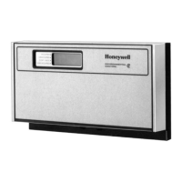
Q7300 Subbase:
Use with T7300D,E,F Thermostats.
Auxiliary contacts can be used to interface with
C7400/W7459 Economizer System for total
integration of rooftop control.
When used with the T7300F (revision 3 or later), the
Q7300H communicates with other network devices.
Contents
Application........................................................................... 1
Features .............................................................................. 1
Specifications ...................................................................... 2
Ordering Information ........................................................... 2
Installation ........................................................................... 5
Wiring Subbase or Wallplate ............................................... 7
Settings ............................................................................... 9
Installer Setup ..................................................................... 10
Installer System Test ........................................................... 14
Programming....................................................................... 16
Operation ............................................................................ 20
General Operation Information............................................ 22
Troubleshooting Guide ........................................................ 23
Cross Reference ................................................................. 25
Wiring Diagrams.................................................................. 33
63-4355-2

Questions and Answers:

Honeywell T7300D Specifications

General IconGeneral
BrandHoneywell
ModelT7300D
CategoryThermostat
LanguageEnglish

Summary

PRODUCT DATA

T7200 D,E Thermostats

Details applications for single-stage conventional or heat pump systems.

T7300 D,E Thermostats

Covers multistage conventional or heat pump applications, with remote sensor capability.

T7300 F Thermostats

For single or multistage systems, conventional or heat pump, with auxiliary contacts and remote sensors.

Q7300 Subbase

Used with T7300D, E, F thermostats, featuring auxiliary contacts for economizer integration.

FEATURES

All Models

Lists common features like 7-day programming, multiple periods, P+I control, and Intelligent Recovery.

SPECIFICATIONS

T7200 T7300 Thermostat Features

Details features for T7200 and T7300 thermostats as listed in Table 1.

Q7300 Subbase Features

Details features for Q7300 subbases as listed in Table 2.

ORDERING INFORMATION

Contact and Support Information

Provides contact details for questions, information, or comments on products and services.

SPECIFICATIONS DETAILS

Electrical and Temperature Ratings

Covers electrical ratings, operating/shipping temperatures, display accuracy, and setpoint range.

Performance and Operational Specs

Details minimum stage operation, humidity, clock accuracy, and mounting means.

Accessories and Approvals

Lists available accessories, product approvals, and recycling instructions.

DIMENSIONS

Subbase Dimensions

Provides dimensional drawings for Q7300A, C, D, G, L, and Q7300H subbases.

Thermostat Dimensions

Shows dimensions for T7200D/E and T7300D/E/F thermostats, noting wallplate differences.

INSTALLATION GUIDELINES

General Installation Steps

Emphasizes reading instructions, checking ratings, and using experienced technicians.

Thermostat and Sensor Location

Guides placement for thermostats and sensors to ensure accurate temperature sensing.

Sensor Placement Avoidance

Details what to avoid when placing sensors, like drafts, heat sources, and unheated areas.

WIRING AND MOUNTING

Electrical Interference Prevention

Advises on keeping wiring short and using shielded cable to prevent interference.

Temperature Averaging Wiring Diagrams

Illustrates wiring for temperature averaging networks with various sensor configurations.

SubbaseWallplate Mounting

Details steps for mounting subbases or wallplates horizontally on walls or wiring boxes.

WIRING SUBBASE OR WALLPLATE

Mounting Procedure Details

Describes drilling holes, positioning the subbase/wallplate, and securing mounting screws.

Wiring Compliance and Safety

States wiring compliance requirements and warns of electrical shock hazards.

TERMINAL DESIGNATIONS

Economizer and Relay Terminals

Explains terminals A1, A2, A3 for economizer control, and terminals for fan, emergency heat, and changeover.

Transformer and Sensor Terminals

Covers terminals for system transformers and remote sensors.

TERMINAL DESIGNATIONS CONTINUED

Heating, Cooling, and LED Terminals

Lists terminals W1-W3 for heating, Y1-Y3 for cooling, and X, X1-X4 for LEDs and common.

Actuator and Control Terminals

Explains terminals for actuators (BM, RM) and specific controls like HSII Control Panel.

Wiring Best Practices

Advises using 18-gauge solid-conductor cable and proper wire connection techniques.

THERMOSTAT MOUNTING

Engaging and Latching Thermostat

Describes how to engage thermostat tabs and latch the lower edge to the subbase or wallplate.

Thermostat Removal

Provides instructions on how to remove the thermostat from the wallplate.

SETTINGS OVERVIEW

Using Thermostat Keys

Explains the functions of various thermostat keys for setting time, programming, and configuration.

System and Fan Settings

Details how to set system (Heat, Off, Cool, Auto) and fan (On, Auto) operations.

Temperature Settings

Guides users to refer to temperature setpoint tables and programming sections.

THERMOSTAT KEY LAYOUT

Key Functions Description

Identifies and describes the function of each key on the thermostat keypad.

INSTALLER SETUP

Accessing Installer Setup Mode

Explains the key combination required to enter the Installer Setup mode.

Installer Setup Display Information

Describes the display segments and numbers shown during Installer Setup.

THERMOSTAT INSTALLER SETUP OPTIONS

Installer Setup Navigation and Fan Configuration

Details setup navigation, fan operation, and heating/cooling stage configuration.

System and Display Settings

Covers options for system setting adjustment and degree temperature display.

THERMOSTAT INSTALLER SETUP OPTIONS CONTINUED

Display, Clock, and Lockout Settings

Covers settings for displaying temperature, clock format, and keypad lockout levels.

Fan, Auxiliary, and Remote Sensing Settings

Details configurations for Intelligent Fan, auxiliary contact, and remote sensing.

Override Duration and Deadband

Covers settings for temporary override duration and deadband for setpoints.

THERMOSTAT INSTALLER SETUP OPTIONS CONTINUED

Interstage Control and Minimum Times

Details settings for interstage control points and minimum on/off times for heating and cooling.

Temperature Range Stops and Display Adjustment

Covers settings for temperature range limits and adjustments to the displayed temperature.

Installer Setup Lockout Activation

Explains how to activate Installer Setup lockout using DIP switch and setup numbers.

SETTING CURRENT TIMEDAY

Setting Current Day and Time

Provides step-by-step instructions for setting the current time and day on the thermostat.

INSTALLER SYSTEM TEST

Initiating System Test

Guides users on how to start the system test by pressing specific keys.

System Test Overview and Available Tests

Introduces the Installer System Test and lists available tests like heating, cooling, and fan.

INSTALLER SYSTEM TEST OPTIONS

Heating and Emergency Heating Tests

Details tests for activating heating and emergency heating stages and the system fan.

Cooling and Fan Equipment Tests

Outlines tests for activating cooling stages and operating the fan.

Key Operation and System Tests

Describes tests to verify key functionality and display thermostat information.

THERMOSTAT INFORMATION

Accessing and Displaying Thermostat Data

Explains how to view production date, software ID, revision number, and EEPROM/subbase codes.

SETTING KEYPAD LOCKOUT

Activating Keypad Lockout via DIP Switch

Details how to activate keypad lockout using DIP switch 1 on the back of the thermostat.

PROGRAMMING FUNDAMENTALS

Programming Overview and Requirements

Introduces programming capabilities and notes the need to disable keypad lockout.

SETTING PROGRAM TIMES

Setting Occupied Start Times

Provides steps to set the start times for Occupied Period 1 and Occupied Period 2.

SETTING CURRENT DAYTIME

Setting Day and Time Procedure

Guides on setting the current day and time using the thermostat keys.

COPYING PROGRAM DATA

Copying Days Start Times

Explains how to copy start times from one day to another using the Copy feature.

SETTING TEMPERATURE SETPOINTS

Setting Occupied Temperature Setpoints

Details steps to set the desired occupied temperature for heating and cooling.

Setting Unoccupied Temperature Setpoints

Guides on setting the desired unoccupied temperature for heating and cooling.

CHANGING TEMPERATURE SETPOINT

Temporary Setpoint Adjustment

Explains how to change the temperature setpoint until the next scheduled program period.

USING TEMPORARY OVERRIDE

Temporary Override Procedure

Provides steps to set a temporary temperature override using the Occupied Temp key.

CLEARING PROGRAM START TIMES

Clearing Programmed Start Times

Guides on clearing programmed start times for occupied and unoccupied periods.

USING CONTINUOUS UNOCCUPIED

Setting Continuous Unoccupied Mode

Explains how to set the thermostat to continuous unoccupied mode.

OPERATION MODES

T7200 T7300 Relay Logic

Describes the relay logic for conventional and heat pump applications.

P+I Control Explained

Explains the proportional plus integral (P+I) control algorithm for precise temperature regulation.

ADVANCED CONTROL ALGORITHMS

P+I Temperature Control Mechanism

Details how proportional and integral errors are calculated and used in temperature control.

EQUIPMENT PROTECTION

Minimum OnOff Time Settings

Explains the importance of minimum on/off times for equipment protection and how they are set.

THERMOSTAT OPERATION MODES

Startup and Initialization

Describes the startup and initialization program that runs when power is applied.

Occupied and Unoccupied Periods

Explains thermostat operation and fan cycling during occupied and unoccupied periods.

Intelligent Recovery Feature

Describes the Intelligent Recovery feature for gradual temperature transitions.

HEATING AND COOLING CHANGEover

O and B Terminal Functions

Explains the role of O and B terminals for changeover and damper/valve control.

FAN AND EMERGENCY HEAT OPERATION

COMMUNICATING SUBBASE

GENERAL OPERATION INFORMATION

Cycle Rate Control

Explains how the thermostat controls temperature by cycling heating or cooling stages.

INTERFACING WITH ECONOMIZERS

Economizer Control via Auxiliary Relay

Details connecting auxiliary relay contacts to control economizer minimum position.

OTHER AUXILIARY RELAY USES

TROUBLESHOOTING GUIDE

Troubleshooting Symptom Table

Provides a table listing symptoms, causes, and actions for troubleshooting issues.

Display and Temperature Setting Issues

Addresses problems like display issues and temperature settings not changing.

Installer Setup and Keypad Lockout Troubleshooting

Covers issues with Installer Setup configuration and keypad lockout.

TROUBLESHOOTING CONTINUED

Setpoint and Room Temperature Issues

Discusses setpoint proximity, deadbands, and room temperature control problems.

Heating and Cooling System Malfunctions

Covers troubleshooting for heating/cooling failures, system selection, and equipment operation.

CROSS REFERENCE INFORMATION

Series 2000 vs. Older Models

Summarizes differences between Series 2000 and older T7300/Q7300 devices.

Q7300 Subbase Cross-Reference

Lists Q7300 subbases with their descriptions, trade replacements, and remarks.

THERMOSTAT AND SUBBASE CROSS REFERENCE

Q7300 C and Q7300 D Subbase Cross-Reference

Lists Q7300C and Q7300D subbases with their trade replacements and remarks.

Q7300 E Subbase Cross-Reference

Lists Q7300E subbases and their trade replacements.

THERMOSTAT AND SUBBASE CROSS REFERENCE

Q7300 F, Q7300 G, Q7300 L Subbase Cross-Reference

Lists Q7300F, G, and L subbases with their trade replacements.

T7200 and T7300 Thermostat Cross-Reference

Cross-references T7200 and T7300 models with their trade replacements.

THERMOSTAT AND SUBBASE CROSS REFERENCE

T7300 A, T7300 B, T7300 C Model Cross-Reference

Cross-references T7300A, B, and C models with their trade replacements.

T8611 M Model Cross-Reference

Cross-references T8611M models, noting wiring differences and sensor requirements.

THERMOSTAT AND SUBBASE CROSS REFERENCE

T8611 M7057, T8611 M7065, T8621 A Models

Cross-references specific T8611M and T8621A models, detailing wiring differences and requirements.

T8621 B and T8621 C Models

Lists T8621B and T8621C models, trade replacements, and wiring differences.

THERMOSTAT AND SUBBASE CROSS REFERENCE

T8621 C7032 and T8621 D Models

Details T8621C7032 and T8621D models, their trade replacements, and wiring differences.

THERMOSTAT AND SUBBASE CROSS REFERENCE

T8621 E, Y7200, Y7300 Models

Cross-references T8621E, Y7200, and Y7300 models with trade replacements and wiring differences.

Series 2000 Cross Reference - Q7300 A

Lists Q7300A subbases in Series 2000 and their direct replacements for T8621A thermostats.

Series 2000 Cross Reference - Q7300 C

Details Q7300C subbases in Series 2000 and their direct replacements for T8611M thermostats.

THERMOSTAT AND SUBBASE CROSS REFERENCE

Series 2000 Cross Reference - Y7300 Models

Cross-references Y7300 models in Series 2000 with trade replacements and wiring differences.

Series 2000 Cross Reference - Q7300 A, C, D, G

Lists Series 2000 Q7300A, C, D, G subbases and their direct replacements.

T7300 Q7300 Series 2000 Cross Reference

Q7300 L Subbases and T7200 T7300 Models

Lists Q7300L subbases and cross-references T7200/T7300 models.

WIRING DIAGRAMS

T7200 D with Wallplate Wiring

Shows the wiring diagram for the T7200D thermostat with a wallplate.

T7200 E Heat Pump System Wiring

Illustrates the wiring diagram for T7200E with a one-stage heat pump system.

WIRING DIAGRAMS CONTINUED

T7300 D,FQ7300 A2008 Conventional System Wiring

Provides hookup diagram for T7300D,F/Q7300A2008 in a one-stage heat/cool system.

T7300 D,FQ7300 A2016 Conventional System Wiring

Shows hookup diagram for T7300D,F/Q7300A2016 in a two-stage heat/cool system.

WIRING DIAGRAMS CONTINUED

T7300 E,FQ7300 C2004 Heat Pump System Wiring

Illustrates hookup for T7300E,F/Q7300C2004 in a heat pump system.

T7300 E,FQ7300 C2012 Heat Pump System Wiring

Provides hookup diagram for T7300E,F/Q7300C2012 in a heat pump system.

WIRING DIAGRAMS CONTINUED

T7300 E,FQ7300 C2053 Heat Pump System Wiring

Shows hookup for T7300E,F/Q7300C2053 in a heat pump system.

T7300 E,FQ7300 D2002 Heat Pump System Wiring

Illustrates hookup for T7300E,F/Q7300D2002 in a heat pump system.

WIRING DIAGRAMS CONTINUED

T7300 D,FQ7300 G2005 Conventional System Wiring

Provides hookup diagram for T7300D,F/Q7300G2005 in a conventional system.

T7300 FQ7300 H2003 Heat Pump System Wiring

Shows hookup for T7300F/Q7300H2003 in a heat pump system without O/B terminals.

WIRING DIAGRAMS CONTINUED

T7300 FQ7300 H2011 Heat Pump System Wiring

Illustrates hookup for T7300F/Q7300H2011 in a heat pump system with O/B terminals.

T7300 FQ7300 H2029 Conventional System Wiring

Provides hookup diagram for T7300F/Q7300H2029 in a conventional system.

WIRING DIAGRAMS CONTINUED

T7300 FQ7300 H2037 Conventional System Wiring

Shows hookup for T7300F/Q7300H2037 in a conventional system.

T7300 FQ7300 H Devices in LonWorks Network

Illustrates typical hookup for T7300F/Q7300H devices within a LonWorks® network.

WIRING DIAGRAMS CONTINUED

T7300 D,FQ7300 L2004 System Wiring

Provides hookup diagram for T7300D,F/Q7300L2004 with valve actuators.

Related product manuals