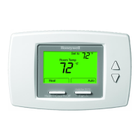
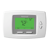
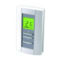
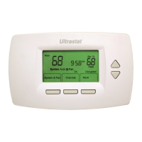
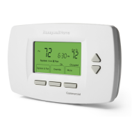
TB6575/TB8575 SUITEPRO™ DIGITAL FAN COIL THERMOSTATS INSTALLATION
62-0278—01 4
Fig. 2. Mounting sub-base and thermostat to 2 x 4 in. junction box.
Fig. 3. Mounting sub-base and thermostat using the adaptor plate (50033847-001).
Terminal Wiring
Table 3 on page 5 provides the terminal wiring for each model
and application.
NOTE: The TB6575A1000 and TB6575B1000 models have
color coded fly leads attached to the terminals. Refer
to Table 3 for the color codes.
The Terminal Identifiers in Table 3 have the following meaning:
• C: Common 24 Vac
• Gh: High speed fan relay
• Gl: Low speed fan relay
• Gm: Medium speed fan relay
• L: Line voltage power (120/240 Vac)
• N: Line voltage ground (120/240 Vac)
• Ps: Pipe sensor (optional)
• R: 24 Vac power
• Rs: Remote sensor (optional)
• SB: Remote setback (optional)
• Sc: Ground (required if remote sensor, pipe sensor, and/or
remote setback are connected)
• W/Y: W = Heating; Y = Cooling (2 pipe only)
• Y/A: Y = Cooling; A = Electrical heater output
M27590
INSERT SCREW TO LOCK
MAIN BODY TO SUBBASE
SNAP MAIN BODY
ONTO SUBBASE
MOUNT SUBBASE TO
HORIZONTAL 2X4
JUNCTION BOX USING
TWO SCREWS
SUBBASE
M27591
INSERT SCREW
TO LOCK MAIN
BODY TO
SUB-BASE
SNAP MAIN BODY
ONTO SUB-BASE
SUB-BASE
MOUNT ADAPTOR PLATE ONTO
4X4 WIRING BOX OR 2X4
VERTICAL JUNCTION BOX
USING TWO SCREWS
ADAPTOR
PLATE
SCREW HEAD
COVER
ADAPTOR
PLATE
MOUNT SUB-BASE
ONTO WALL PLATE
USING TWO SCREWS
NOTE: MIDDLE HOLES OF ADAPTOR PLATE ARE USED FOR MOUNTING
TO A 2X4 VERTICAL JUNCTION BOX. USE OUTER HOLES FOR
MOUNTING TO A 4X4 WIRING BOX.
 Loading...
