INSTALLATION TB6575/TB8575 SUITEPRO™ DIGITAL FAN COIL THERMOSTATS
3 62-0278—01
Dimensions
Fig. 1. Dimensions in inches and mm.
INSTALLATION
When Installing this Product…
1. Read these instructions carefully. Failure to follow them
could damage the product or cause a hazardous
condition.
2. Check the ratings given in the instructions and on the
product to make sure the product is suitable for your
application.
3. Installer must be a trained and experienced service
technician.
WARNING
Risk of electrical shock.
Can cause severe injury, property damage or
death.
Disconnect power supply before installation and
before servicing.
IMPORTANT
The thermostats are line voltage powered devices. All
wiring must comply with national and local electrical
codes, ordinances and regulations. Provide disconnect
means and overload protection, as required.
The TB8575A1000 thermostat must be powered by an
Approved 24 Vac, Class 2, NEMA rated transformer
(such as a W6380 Relay Control Center).
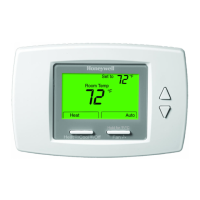
Location
The thermostats are the temperature control element in a fan coil
or air-conditioning system. They must be located about 1.5m
(5 ft.) above the floor, in a position with good air circulation, to
sense room temperature.
IMPORTANT
Do not mount device where it can be affected by:
1. Drafts or dead spots behind doors or in corners.
2. Hot or cold air from ducts.
3. Radiant heat from the sun or appliances.
4. Unheated (uncooled) areas such as an outside wall
behind the thermostat.
5. Concealed pipes or chimneys.
Mounting and Wiring
CAUTION
Equipment Damage Hazard.
Operation at low temperatures can cause fan
coil damage.
This thermostat is not a safety device. Do not use
it where the space temperature is outside of the
device operating range.
A display of two dashes, – –, for the Room Temp
display indicates a sensor failure or a
temperature outside of the thermostat operating
range of 18°C to 49°C (0°F to 120°F). With – –
displayed, the thermostat ceases to operate.
When the temperature returns to within its
operating limits, the thermostat returns to
operation.
The optional freeze protect feature should be used
if low temperatures can occur.
The thermostat must be mounted flush to the wall. The
thermostat can be mounted directly to a 2 x 4 in. horizontal
junction box (see Fig. 2 on page 4). An optional adaptor plate
(50033847-001) can be used with a 4 x 4 in. or a vertical junction
box for which mounting screws are supplied (see Fig. 3 on
page 4).
1. Prepare the supply wires:
a. Mounting on a 4 x 4 in. or vertical 2 x 4 in. junction
box:
(1) Feed the supply wires through the junction box
and the opening in the adaptor plate.
(2) Affix the adaptor plate to the junction box using
the screws provided.
b. Mounting on a horizontal 2 x 4 in. junction box:
Feed the supply wires through the opening of the
junction box.
2. Attach the supply wires:
a. For the TB6575A1000 and TB6575B1000 models:
(1) Push the fly lead wires through the wiring access
hole in the sub-base.
(2) Attach the fly lead wires to the supply wires using
wire nuts (not provided).See Table 3 on page 5 for
terminal and lead identification.
(3) Push the fly lead and supply wires back into the
junction box.
b. For the TB8575A1000 model (which does not have
pre-wired fly leads):
(1) Attach the supply wires directly to the terminals on
the sub-base. See Table 3 on page 5 for terminal
identification.
(2) Push the supply wires back into the junction box.
3. Mount the sub-base:
a. Mounting on a 4 x 4 in. or vertical 2 x 4 in. junction
box:
Align the two holes at the top edges of the sub-base
with the two pins on the adaptor plate. Attach the
sub-base to the adaptor plate using the screws
provided.
b. Mounting on a horizontal 2 x 4 in. junction box:
Attach the sub-base to the junction box using the
screws provided.
4. Thoroughly check the wiring to the sub-base before finally
mounting the thermostat on the wall.
5. Center the thermostat body over the sub-base, and press
down firmly to engage the four tabs on the sub-base and
snap the thermostat body into place.
6. Use the provided safety screw to secure the thermostat
main body to the sub-base.
7. If using the adaptor plate, press the adaptor plate screw
cover into place.
M27589
UP
5-13/16 (148)
3-13/16
(97)
1-1/8
(29)
THERMOSTAT
SUB-BASE
3-1/4 (83)
2-3/8 (60)
1-3/4
(44)
5/32
(4)
5/32
(4)
1-3/16
(30)
 Loading...