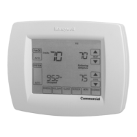
TB7220U ULTRASTAT PROGRAMMABLE THERMOSTAT
11 62-0223—1
0250 CPH for second
stage conventional
heat
9 1-12 Only shown for conventional system with at least
two stages conventional heat or 2H/1C heat pump
(ISU 0170).
0260 CPH for third Stage
Heat
9 1-12 Only shown for 3H/2C heat pump system
(ISU 0170).
0270 CPH for Auxiliary
Heat
9 1-12 Only shown for multi-stage heat pump system with
more heat than cool stages (ISU 0170).
0280 Continuous
Backlight
0 0—No
1—Yes
Always shown. If AC power not present the option
is overridden and normal backlight operation
occurs.
0300 Changeover 1 0—Manual
1—Auto
Only shown for system with both heat and cool
stages (ISU 0170).
0310 Deadband 3°F
(2°C)
2 (1.5)—2°F (1.5°C)
3 (2.0)—3°F (2.0°C)
4 (2.5)—4°F (2.5°C)
5 (3.0)—5°F (3.0°C)
6 (3.5)—6°F (3.5°C)
7 (4.0)—7°F (4.0°C)
8 (4.5)—8°F (4.5°C)
9 (5.0)—9°F (5.0°C)
Only shown for Auto Changeover system
(ISU 0300).
0320 Temperature
Indication Scale
0 0—°F
1—°C
0330 Daylight Saving 2 0—Disabled
1—Enabled (US 1987)
2—Enabled (US 2007)
3—Enabled (Europe)
0340 Remote
Temperature
Sensor
0 0—None
1—Outdoor for Display
2—Outdoor for Control
3—Remote 10K Indoor
4—Remote 20K Indoor
Averaging would not include on-board sensor. It is
accomplished by series/parallel combinations.
2 applies only to Heat Pump applications (allowing
compressor lockout while displaying temperature).
0350 Heat Pump
Compressor
Lockout
0 0—None
15(-9.5)—15°F (-9.5°C)
20(-6.5)—20°F (-6.5°C)
25(-4.0)—25°F (-4.0°C)
30(-1.0)—30°F (-1.0°C)
35 (1.5)—35°F (1.5°C)
40 (4.5)—40°F (4.5°C)
45 (7.0)—45°F (7.0°C)
Only shown for heat pump systems with more heat
stages than cool (ISU 0170) and remote outdoor
control sensor (ISU 0340 at 2).
Requires a deadband between this and the
Auxiliary Lockout (ISU 360).
0360 Heat Pump
Auxiliary Lockout
0 0—None
40(4.5) — 40°F (4.5°C)
45(7.0) — 45°F (7.0°C)
50(10.0)—50°F (10.0°C)
55(13.0)—55°F (13.0°C)
60(15.5)—60°F (15.5°C)
Only shown for heat pump systems with more heat
stages than cool (ISU 0170) and remote outdoor
control sensor (ISU 0340 at 2).
Requires a deadband between this and the Heat
Pump Compressor Lockout (ISU 350).
0535 Temporary
Occupied Duration
Limit
3 0—no duration
1—one hour
2—two hours
3—three hours
4—four hours
0 means no limit.
0540 Number of Periods 4 2—2 Periods
4—4 Periods
Does not appear with Non-programmable chosen
(ISU 0160 at 0).
Applies to all days of the week.
0580 Minimum
Compressor Off
Time
50—Off
2—2 minutes
3—3 minutes
4—4 minutes
5—5 minutes
Only shown if system has cool stages (ISU 0170).
0600 Heat Temperature
Range Stops
90 40 to 90°F (4 to 32°C) Only shown if system has heat stages (ISU 0170).
0610 Cool Temperature
Range Stops
50 50 to 99°F (10 to 37°C) Only shown if system has cool stages (ISU 0170).
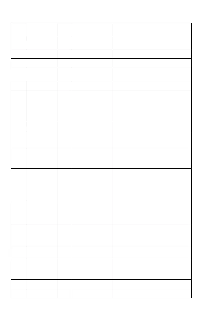
Table 4. Installer Setup Menu. (Continued)
Installer
Setup
Number
Installer Setup
Name
Default
Setting All Settings Notes
 Loading...