TB7220U ULTRASTAT PROGRAMMABLE THERMOSTAT
62-0223—1 2
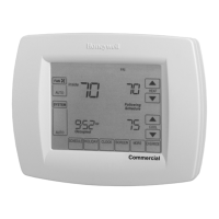
Separate Wallplate from Thermostat
1. Separate the wallplate from the thermostat. See
Fig. 2.
Fig. 2. Separate wallplate from thermostat.
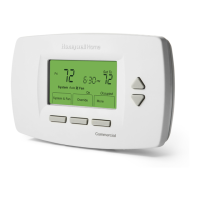
Install Wallplate (See Fig. 3)
Mount the thermostat horizontally on the wall:
1. Pull the wires through the wire hole on the wallplate.
2. Position the wallplate on the wall with the arrow
pointing up. Level the wallplate for appearance only.
3. Use a pencil to mark the mounting holes.
4. Remove the wallplate from the wall and drill two
3/16 in. holes in the wall (if drywall) as marked. For
firmer material such as plaster, drill two 7/32 in.
holes. Tap the wall anchors (provided) into the
drilled holes until flush with the wall.
5. Ensure all wires are pulled through the wire hole on
the wallplate.
6. Position the wallplate over the wall anchors.
7. Insert the mounting screws into the wall anchors
and tighten.
Fig. 3. Install wallplate.
WIRING
IMPORTANT
— All wiring must agree with applicable codes,
ordinances and regulations.
— Use 18 gauge thermostat wire. Shielded cable is
not required.
NOTES:
— Sensor wires must have a cable separate
from the thermostat control cable.
— Refer to Table 2 for terminal designation
descriptions.
— See Fig. 6 through 16 for wiring diagrams for
specific equipment applications.
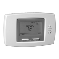
1. Select set of terminal identifications that correspond
to your system type (conventional or heat pump).
(See Fig. 4).
Fig. 4. Terminal identifications for system type.
2. Loosen screw terminals used for the application.
3. Insert the wires into the terminal block and tighten
each screw terminal.
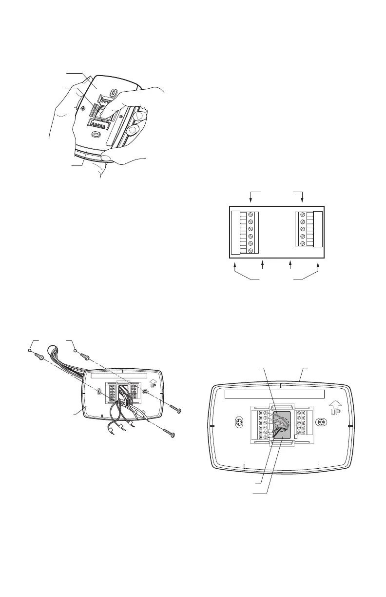
4. Push excess wire back into the wall opening and
restrict wires to the shaded area. See Fig. 5.
5. Plug the wall opening with nonflammable insulation
to prevent drafts from affecting the thermostat.
Fig. 5. Restrict wires to shaded area of wire hole.
THERMOSTAT
WIRE HOLE
M22267
WALLPLATE
M22268
DRILLED
HOLES (2)
WALL
ANCHORS (2)
MOUNTING
SCREWS (2)
WALLPLATE
M23052
C
G
Y
O/B
RC
R
W1
Y2
S1
S2
C
G
Y
W
RC
R
W2
Y2
S1
S2
SCREW
TERMINALS
HEAT PUMP
CONVENTIONAL
WALLPLATE
M22266
WALL OPENING
WIRE
SHADED AREA
 Loading...