EasyManuals Logo

Honeywell UDC2500 Manual

Honeywell UDC2500
8 pages
To Next Page IconTo Next Page
To Previous Page IconTo Previous Page
Page #4 background imageLoading...
Page #4 background image
January 2017 51-52-33-137 4
Table 3: How to Remove the Printed Wiring Boards from the Chassis
Step
Action
1
Remove the chassis from the case as shown in Figure 1.
2
Find J8 in Figure 2. Remove all wire connectors from J8 by sliding a small screwdriver
under each connector and lift the release.
3
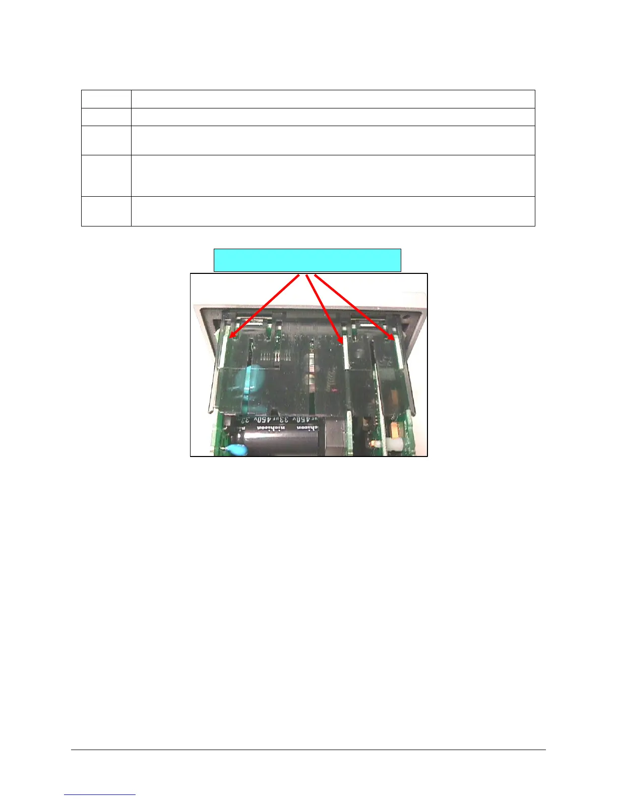
Separate the chassis frame at the release points shown in Figure 3 and ease each
printed wiring board out of its socket on the display/keyboard assembly. Pull all boards
out of the chassis.
4
Lay the boards flat on a static-free surface. If the Display/Keyboard is to be replaced, go
to Table 4. If the Display/Keyboard is not being replaced, go to Table 5.
Figure 3: Removing Printed Circuit Boards
Release points (top and bottom)

Other manuals for Honeywell UDC2500

Questions and Answers:

Question and Answer IconNeed help?

Do you have a question about the Honeywell UDC2500 and is the answer not in the manual?

Honeywell UDC2500 Specifications

General IconGeneral
TypeUniversal Digital Controller
Alarm RelaysUp to 2 alarm relays
CommunicationRS485 Modbus RTU
MountingPanel Mount
DisplayDual 4-digit LED
Input TypesThermocouple, RTD, mA, V
Control ModesOn/Off, PID
Output TypesRelay, mA, V
Power Supply100-240 VAC, 24V DC
Dimensions96x96x132 mm

Related product manuals