January 2017 51-52-33-137 5
Table 4: How to Remove the Display/Keyboard from the Chassis
Remove the chassis from the case as shown in Figure 1.
Remove the Boards from the chassis as shown in Figure 3.
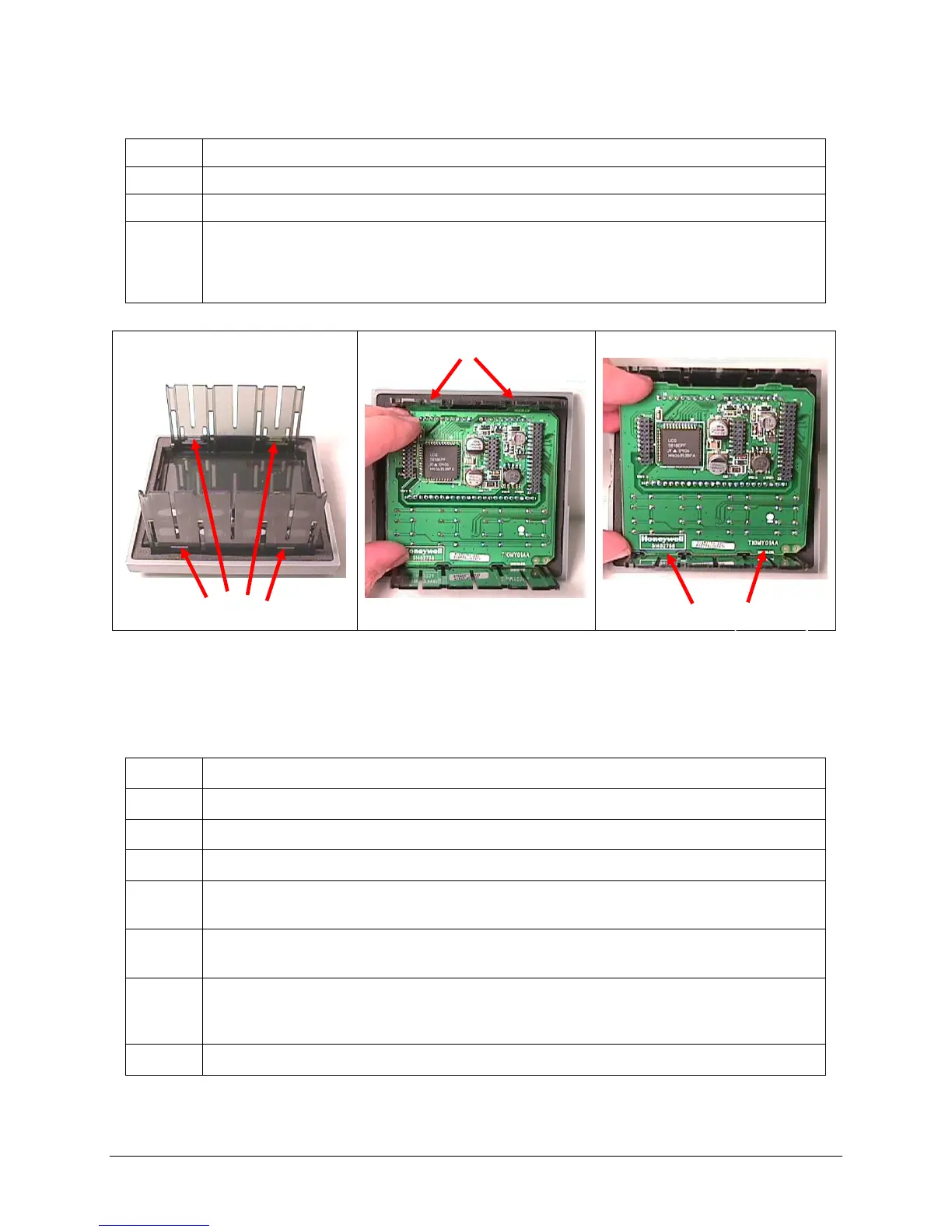
The Display/Keyboard is held in place by four slots in the Chassis as shown in Figure 4.
Using a small flat-blade screwdriver, lift up the two top slots one at a time while pulling
on the Display/Keyboard until it comes out of the slots. Rotate the Display/Keyboard
downwards until it can be pulled out of the bottom two slots.
Figure 4: Removing Display/Keyboard
Table 5: Board Replacement Procedure
Remove the chassis from the case. (Figure 1)
Remove the printed wiring boards from the chassis. (Figure 3 and Figure 4)
Lay the boards flat and identify the board you are replacing. (Figure 2)
If present, the Output option board and the Option Input Board are held onto the
MCU/Input board with three posts. Locate these posts under the MCU/Input board.
Use small pliers and squeeze the ends of each post together and push it up through the
board.
Replace the board with the one from this kit. If the white ground lead on the old board
has a ferrite sleeve on it, remove the sleeve and place it onto the ground lead on the
new board.
Reinstall the Output Option and Option Input boards.

 Loading...


