V4730C/V8730C/V4734C · Edition 05.23
EN-11
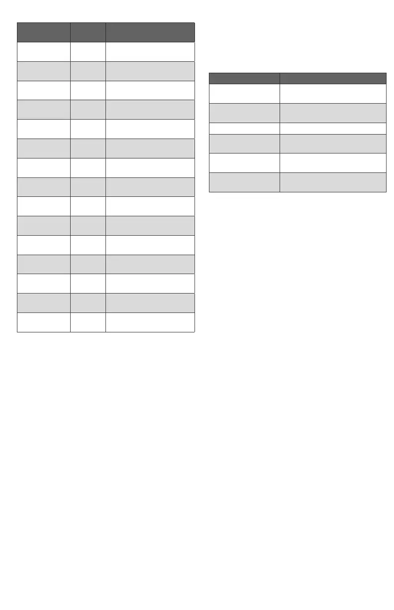
Capacity:
Type VMU
Capacity (natural gas
0.64kg/m
3
)
V4730C1006 150
22–150kW
(73–512 kBtu/hr)
V4730C1014 185
26–185kW
(89–622 kBtu/hr)
V4730C1022 300
43–300kW
(144-1009 kBtu/hr)
V4730C1022 335
48–335kW
(161-1127 kBtu/hr)
V4730C1030 300
43–300kW
(144–1009 kBtu/hr)
V4730C1030 335
48–335kW
(161–1127 kBtu/hr)
V4734C1002 400
55–382kW
(185–1300 kBtu/hr)
V4734C1002 500
71–500kW
(245–1710 kBtu/hr)
V4734C1002 680
97–680kW
(326–2287 kBtu/hr)
V8730C1007 150
22–150kW
(73–512 kBtu/hr)
V8730C1015 185
26–185kW
(89–622 kBtu/hr)
V8730C1023 300
43–300kW
(144–1009 kBtu/hr)
V8730C1023 335
48–335kW
(161–1127 kBtu/hr)
V8730C1031 300
43–300kW
(144–1009 kBtu/hr)
V8730C1031 335
48–335kW
(161–1127 kBtu/hr)
Maximum operating pressure (UL)
1.45psi (100mbar),
except for 1-1/4inch size:
(24V): 1psi (70mbar),
(120V): 1.45psi (100mbar).
CSA Approved to 0.5psi (34mbar).
Torsion and bending stress
Pipe connections meet group 2 according to
EN13611 requirements.
Electrical connections:
Standard plug connector (according DIN43650)
with 36inch (914mm) lead wires.
Valve position indicator lamps:
Inboard (closest to the valve body) - V1.
Outboard - V2.
Ambient temperature range:
5 to +140°F (-15 to +60°C)
Storage temperature = transport temperature:
-20 to +40°C (-4 to +104°F).
Coil insulation solenoid valves:
Class F insulation system.
Body Material:
Aluminum alloy, die-cast.
Strainer:
Fine mesh screen (0.135 in. [0.34mm] diameter).
AISI 303 steel, serviceable after removing inlet flange
screws. Meets EN161 requirements for strainers.
Seals and Gaskets:
Hydrocarbon-resistant NBR and Viton rubber types.
Enclosure: NEMA 1 (IP 40)
11.1 Tightening torque
Recommended tightening torques for the connec-
tion parts:
Screw type Tightening torque
Throttle screw
adjustment
max. 4.4 lb-in
min. 0.35 lb-in
Flanges
max. 8.8 lb-in
min. 0.04 lb-in
Pressure tap plug 62 ± 8.8 lb-in
Pressure switch
mounting
22 ± 13 lb-in
Pressure switch
cover
10.6 ± 1.8 lb-in
Inlet/outlet flange
screw
38 ± 3.5 lb-in
11.2 Perfomance characteristics
Opening time:
Dead time maximum 1 second.
First valve opening: <0,5 second.
Second valve opening: reaches 50% of the adjusta-
ble outlet pressure within 5 seconds.
Maximum allowable leakage:
Outerwall, safety valve and main valve = 2.5inch
3
/h
(40 cm
3
/h for upto DN 25 and 3inch
3
/h (50 cm
3
/h)
for DN 32 at test pressure of 0.87psi (6mbar) and
1.5 x maximum operating pressure.
High pressure test:
In the “OFF” condition, the valve will withstand
21.75psi (1.5bar) inlet pressure without damage.
Operational voltage range:
The combination gas valve will function satisfactorily
between 85% and 110% of the rated voltage.
Gas Valve Connection to Venturi (Field-Assembled):
Four screws and an O-ring are used to connect the
gas valve to the venturi/manual shutoff valve.
The metal tube provided with the venturi must be
connected between the venturi and the gas valve
regulator.
Fan Connection:
The venturi is connected to the fan using six bolts
(which are included with VMU).
Minimum Load:
The minimum load for which the system can be
used is 14–17% of the reference load, which equals
a minimum pressure differential of 0.2inch WC
(50Pa) of the 1:1 venturi/servo regulator gas control.

 Loading...


