V4730C/V8730C/V4734C · Edition 05.23
EN-3
3
Use new, properly reamed, pipe, free from chips.
4
Apply a moderate amount of good quality pipe
dope, resistant to the action of liquefied
petroleum (LP) gas, only on the pipe threads.
5
Screw the flanges onto the pipes.
6
Ensure that the inlet and outlet flanges are in line
and separate from each other enough to allow
the valve to be mounted between the flanges
without damaging the “O”-ring.
7
Make sure O-ring sealing surfaces are clean.
8
Using general purpose lithium grease, grease the
O-ring.
9
Install the O-ring into the O-ring groove provided
on the valve body (one O-ring per groove).
10
Mount the gas valve between the flanges using
the bolts for each flange.
11
Complete the electrical connections as
instructed in the Electrical Connection section.
12
Complete the electrical connections as
instructed in the wiring section.
3.3 Connections
There are 1/8inch (3mm) NPT pressure taps at the
flanges. At the main body flange connections are
provided to mount either an:
– pressure switches (min. or max.)
– valve proving system (VPS)
3.3.1 Pressure tap points
The following pressures can be measured:
1 Inlet pressure
2 Inlet pressure
3 Interim pressure - unreguleted (pressure between
the two shut-off valves)
4 Outlet pressure - reguleted
P Pilot gas pressure
➔ The corresponding numbers can be found on the
sides of the valve. Pressure points 1 and 4 are
located on top of the flanges.
➔ A pressure switch can be mounted to 2, P or 3.
(C60VR: Only 2 and 3)
1 4
2
Pressure tap points for small body size models.
4
1
2
Pressure tap points for large body size model
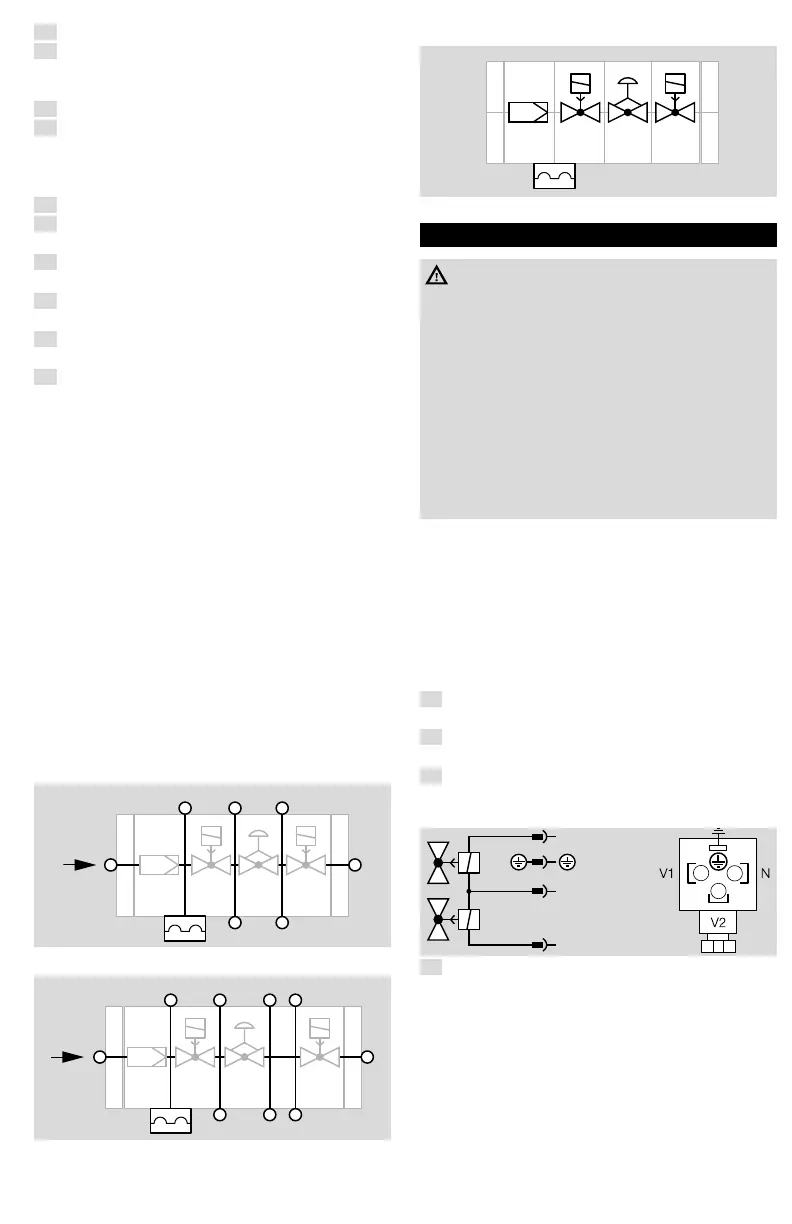
3.3.2 Legend
Strainer
regulator
switch
V1
(SSOV)
V1
(SSOV)
Safety
shut-off valve
4 WIRING
WARNING
Risk of injury!
Please observe the following to ensure that no
damage occurs:
– Electric shocks can be fatal! Before working on
possible live components, ensure the unit is
disconnected from the power supply.
– Switch off power supply before making electrical
connections.
– All wiring must comply with local codes,
ordiances and regulations.
– Use lead wire which can withstand 105°C
ambient.
➔ Use 14, 16 or 18 AWG copper conductor, 600
volt insulation, moisture-resistant wire for line
voltage connections.
➔ Recommended wire types are TTW60C,
THW75C or THHN90C.
– T1 (yellow) will be L2 (120 or 24V AC).
– T2 (black) will be L1 (120 or 24V AC) to Valve 1.
– T3 (blue) will be L1 (120 or 24V AC) to Valve 2.
– Ground (green) will be earth ground.
1
Disconnect the system from the electrical power
supply.
2
Shut off the gas supply.
➔ Before wiring, the fitter should ground himself.
3
Wire as shown on the connection diagram.
➔ Three pin electrical plug connector according to
ISO 4400/DIN43650 (Form A).
1
2
3
V1
1 = N
3 = L1
A
4
After successful wiring, continue with page
4 (5 Tightness test) and page 7 (6.1
Adjust valve).

 Loading...


