V4730C/V8730C/V4734C · Edition 05.23
EN-2
2 CHECKING THE USAGE
The 1:1 Gas/Air Servo Regulated Valves, with an
additional venturi mixing unit (VMU) and a fan, are
used for modulating premixing units, such as gas
burners, gas boilers, roof units, fresh air units and
process applications.
This function is only guaranteed when used within
the specified limits – see page 10 (11 Technical
data). Any other use is considered as non-compliant.
See instruction sheet VMU "VMU Series Venturi
Mixing Unit for V473xC/V873xC Combination Gas
Controls" www.docuthek.com.
Check the ratings given in the instructions and on
the product to make sure the product is suitable for
your application.
2.1 Type code
V Safety shut-off valve
4 Line voltage
73 Combination control
0 Small body size models
4 Large body size models
C Integrated gas/air 1:1
xxxx Specification number
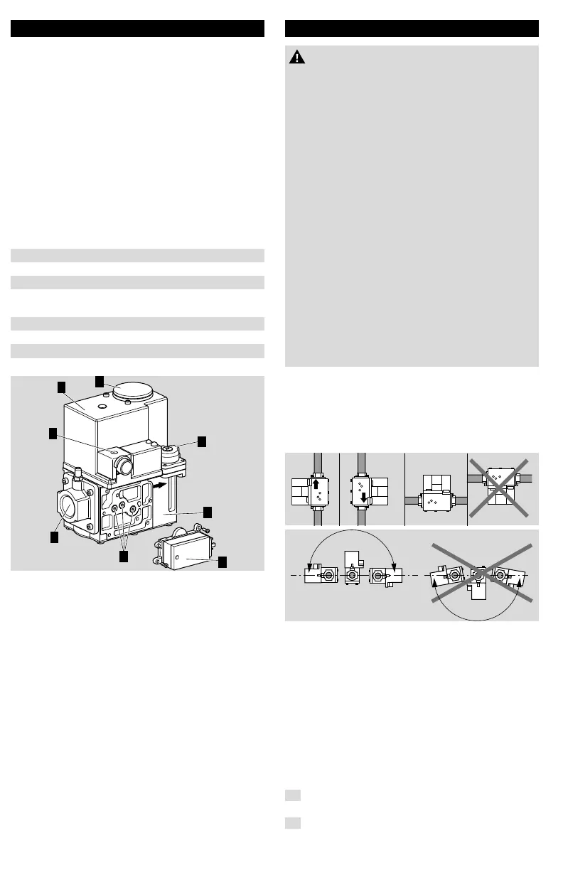
2.2 Part designations
4
6
1
5
2
8
7
1 Main body
2 Cover
3 Cap
4 Servo regulator gas/air 1:1
5 Pressure tap points
6 Inlet flange
7 Electrical connection
(connector type: ISO 4400/DIN43650 Form A)
8 Pressure switches (Option)
3 INSTALLATION
CAUTION
Incorrect installation
Please observe the following to ensure that the
unit is not damaged during installation and oper-
ation:
– Sealing material and dirt, e.g. thread cuttings,
must not be allowed to get into the valve
housing.
– Dropping the device can cause permanent
damage. In this event, replace the entire device
and associated modules before use.
– Turn off gas supply before installation.
– Disconnect power supply to the valve actuator
before beginning the installation to prevent
electrical shock and damage to the equipment.
– Do not remove the seal over valve inlet and
outlet, until ready to connect piping.
– The valve must be installed so that the arrow on
the valve points in the direction of the gas flow
(gas pressure helps to close the valve).
– Screws which are protected against unauthor-
ised removal must not be loosened. This will
invalidate the warranty!
3.1 Installation position
Solenoid actuator in the vertical upright position or
tilted up to the horizontal, not upside down.
Gas valves with integrated gas/air 1:1: The factory
settings are made in a horizontal installation position.
A vertical installation may require readjustments.
The distance between the gas valve and the wall/
ground, must be at least 30 cm.
➔ The valve can be mounted up to ±90 degrees
from this position without affecting the fuel/air
metering at medium and high firing rates (3000
to 5000 rpm of the blower), but at lower firing
rates (1000 rpm) the fuel might be reduced up
to 10% when the valve is not mounted horizontal.
To counter this, the low fire gas flow may be
carefully field adjusted for non-horizontal mount-
ing as described below.
3.2 Install valve
1
Take care that dirt does not enter the gas valve
during handling.
2
Remove flanges from the valve (if factory
mounted).

 Loading...


