V4730C/V8730C/V4734C · Edition 05.23
EN-9
9 TROUBLESHOOTING
WARNING
Risk of injury!
Can cause severe injury, death of property dam-
age.
– Use extreme caution when troubleshooting; line
voltage is present.
– Do not replace the valve until all other sources
of trouble are eliminated.
?
Fault
!
Cause
• Remedy
?
The valve does not open when the thermo-
stat or controller calls for heat?
!
No voltage at the valve lead wires.
• Check for voltage at the valve lead wires or
terminal block.
!
If there is no voltage at the valve lead wires or
terminal block.
• Make sure, that voltage is connected to the
master switch.
• Make sure, that the master switch is closed
and overload protection (circuit breaker, fuse,
or similar device) has not opened the power
line.
!
There is still no voltage at the valve lead wires.
• If there is still no voltage at the valve leadwires
or terminal block, make sure all appropriate
contacts in the thermostat or controller, limits
and flame safeguard control are closed. If one
or more are open, determine the cause(s);
correct the trouble and proceed.
!
There is proper voltage at the valve but the valve
still does not open.
• check for normal gas pressure.
!
Is it not possible for the fault to be eliminated
with the measures described above?
• Remove the unit and return it to the manufac-
turer for inspection.
?
If the valve does not close when one or
more of the appropriate contacts in the
thermostat, controller, limits or flame safe-
guard control is open.
!
Is the valve connected in the correct circuit?
• Make sure the valve is wired in the correct
circuit
!
Valve is not wired correctly.
• Open the master switch to remove power
from the valve. If the valve closes now, check
the wiring for the valve and correct the wiring
as necessary.
!
Is there a short circuit?
• Check for a short in the electrical circuit and
repair it as necessary.
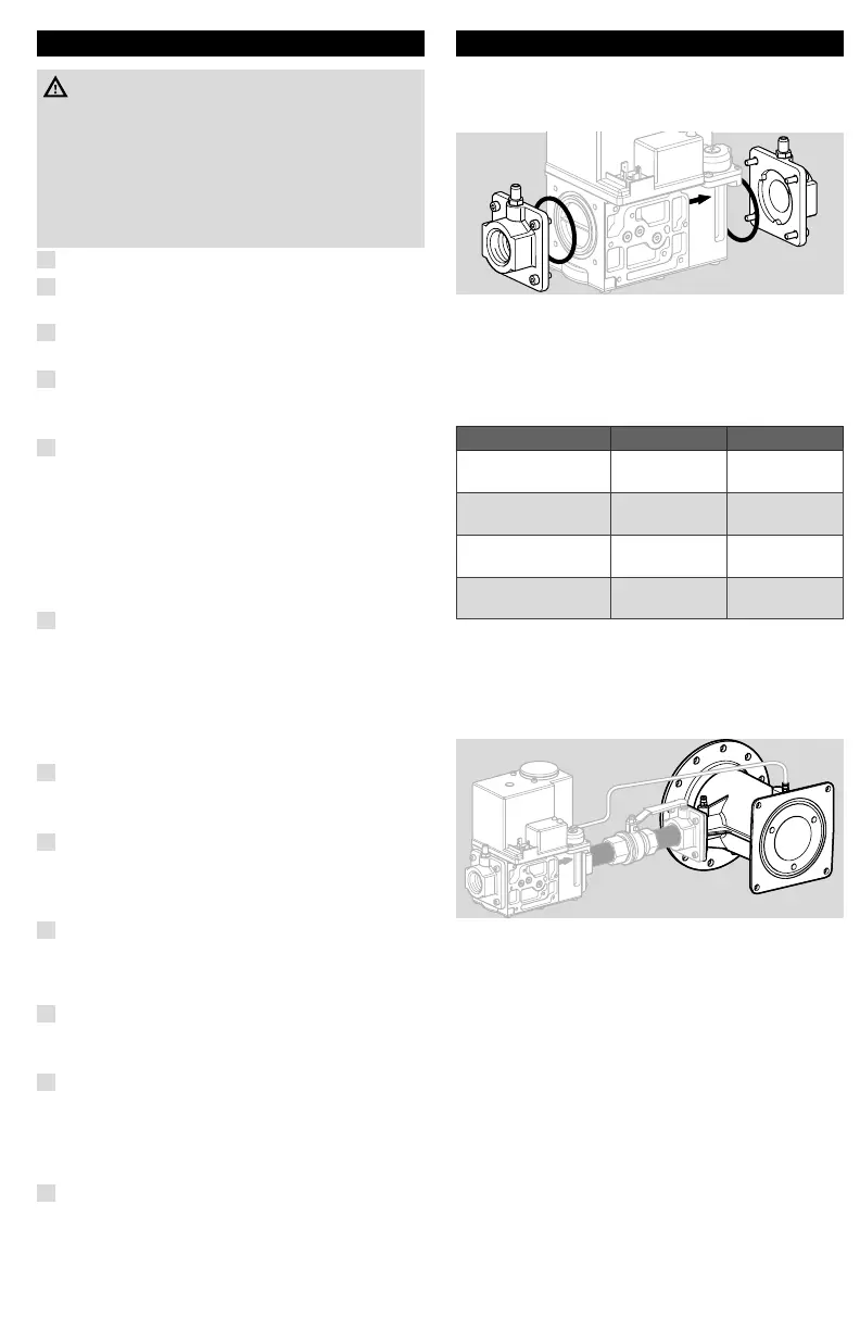
10 ACCESSORIES
10.1 Flange kit
Inlet flanges and outlet flanges are available as
accessories. Valve comes with one kit only.
Scope of delivery:
1 flange with sealing plug,
1 “O”-ring and screws,
1 pressure tap nipple fitted
Flange kits
Pressure tap included?
Part number Size (NPT) Remarks
32006652-001 1/2"
pressure tap
1/8"
32006652-002 3/4"
pressure tap
1/8"
32006652-003 1”
pressure tap
1/8"
32006652-004 1¼”
pressure tap
1/8"
10.2 Valve connection plug
Electrical connections Standard DIN plug connector
according DIN43650 (Form A)
-CO020012 (black). Not included.
10.3 Mixing unit VMU
Integrated gas/air 1:1 with venturi mixing unit, see
instruction sheet VMU "Mixing unit for V473xC/
V8743xC gas controls" (65-0282) www.docuthek.
com.
10.4 Venturi-mounting-kit
For flange mounting the Venturi VMU. Order no.:
32006653-001.
Scope of delivery: O-rings/screws.

 Loading...


