22
V32FB-004-V0
TELCO LINE
BATTERYBATTERY
XFMR
NOT TO SCALE
FUSE
TIE WRAP
TO CABINET
ZONE
AND
BELL
WIRING
MAKE SURE THAT
TERMINAL 2 (XFMR
SECONDARY WIRE)
AND TERMINAL 3
(BELL WIRE) ARE
TERMINATED AS
SHOWN TO MAINTAIN
1/4" MIN. SPACING.
DETAIL A
NOTE: NON POWER-LIMITED
WIRING (AC, BATTERY) MUST
BE SEPARATED FROM
POWER-LIMITED WIRING
(ZONES, BELLS, ECP, POLLING
LOOP) BY 1/4-INCH (6.4 mm)
Figure 3-2: Separation of Circuits
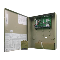
Installing the Control's Circuit Board
To install the circuit board in the cabinet, perform the following steps:
Step Action
1
Install the nylon standoffs (supplied) into the top corner holes of the mounting plate (Figure 3-3, Detail A.)
Insert the top of the circuit board onto the two standoffs at the top of the mounting plate.
2
Place the board flat and secure to the mounting plate with the three accompanying screws and spacers as
shown (Detail B.)
NOTES:
• Make sure that the mounting screws are tight. This ensures that there is a good ground connection between the PC
board and the cabinet.
• Dress field wiring away from the microprocessor (center) section of the PC board. Use small holes in the sidewalls of
the cabinet for anchoring field wiring using tie wraps (Figure 3-3).
V32FB-005-V0
PC BOARD
PLATE
CABINET
SPACER
DETAIL B
SIDE VIEW,
PC BOARD INSTALLATION
USING SPACERS (3) AND
MOUNTING SCREWS (3)
MOUNTING
SCREW
PLATE
CABINET
DETAIL A
INSTALLING
NYLON STANDOFFS (2)
Figure 3-3: Mounting the PC Board

 Loading...