41
TO CONTROL'S REMOTE KEYPAD
CONNECTION POINTS. EACH RECEIVER
MUST BE ON INDIVIDUAL HOME RUN.
USE MAX. of 220 ft. [67m of #22 (0.64mm)
WIRE or 550 ft. (168m) of #18 (1mm) WIRE
FOR EACH RUN. OBSERVE 20 ft. MAX.
FOR COMMERCIAL FIRE INSTALLATIONS.
(SEE RECEIVER'S INSTRUCTIONS.)
DIP SWITCH WHITE AREAS = SWITCH
HANDLES. POSITION 2-4 DETERMINE
RECEIVER'S ADDRESS. CONSULT
CONTROL'S INSTRUCTIONS FOR
ADDRESS TO USE. DIP SWITCH BELOW
SHOWN SET FOR ADDRESS "0."
SWITCH
POSITION
RECEIVER ADDRESS SETTINGS
(" - " MEANS OFF)
0 1 2 3 4 5 6 7
4
3
2
1
5
PRESENT ONLY ON 5881EH (SEE TEXT AT LEFT)
ON ON ON
ONON
ONON ONON
ONON
ON
FOR FUTURE USE
DIP SWITCH #5 (PRESET ONLY ON 5881EH)
ON: SETS 5881EH FOR USE IN COMMERCIAL
FIRE APPLICATIONS (SEE THE RECEIVER'S
INSTRUCTIONS)*.
OFF: USE IN NON-COMMERCIAL FIRE
INSTALLATIONS.
* FOR COMMERCIAL FIRE APPLICATIONS
THE 5881EH PC BOARD MUST BE MOUNTED
IN A SEPARATE CABINET (SEE RECEIVER'S
INSTRUCTIONS FOR DETAILS).
MOUNTING
HOLES
INSERT IN
RIGHT-HAND
TERMINALS
CIRCUIT
BOARD
DIP SWITCH
YELLOW
RED
BLACK
GREEN
INTERFERENCE
INDICATOR LED
WIRING
OPENING
PLUG & SOCKET
ANTENNAS
5881-001-V0
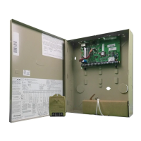
Figure 3-20: 5881ENHC RF Receiver (cover removed)
5800 Series Transmitter Setup
• Transmitters have built-in serial numbers that must be enrolled in the system using the #93 Menu Mode
Programming, or via the downloader.
• Some transmitters can support more than one “zone” (loops or inputs) (e.g., 5817CB). Each loop must be assigned a
different zone number.
Transmitter Supervision
Supervised RF transmitters send a check-in signal to the receiver at 70–90 minute intervals. If at least one check-in is
not received from each supervised transmitter within a programmed period (field 1∗31), the “missing” transmitter
number(s) and “CHECK” or “TRBL” are displayed.
Some transmitters have built-in tamper protection, and annunciate a “CHECK” or “TRBL” condition if covers are
removed.
If a loss of supervision occurs on a transmitter programmed for Fire, it reports in Contact ID as a Fire Trouble
(373), not Loss of Supervision (381), to the central station.
Transmitter Input Types
All transmitters have one or more unique factory-assigned input (loop) codes. Transmitters can be programmed as one
of the following types:
Type Description
RM (RF Motion)
Sends periodic check-in signals, fault and low-battery signals. The control panel automatically restores the
zone to “ready” after a few seconds. It is intended for facilities with multiple motion detectors that may fault
and restore simultaneously. The transmitter must remain within the receiver’s range.
NOTE: RF Motion may only be used on loop 1 of a door/window type transmitter.
RF (Supervised RF)
Sends periodic check-in signals, fault, restore, and low-battery signals. The transmitter must remain within
the receiver’s range.
UR (Unsupervised RF)
Sends all the signals that the RF type does, but the control does not supervise the check-in signals. The
transmitter may be carried off-premises.
BR (Unsupervised Button
RF)
These send only fault signals. They do not send low-battery signals until they are activated. The
transmitter may be carried off-premises. Not applicable in Commercial installations.
Transmitter Battery Life
Batteries in the wireless transmitters may last from 4 to 7 years, depending on the environment, usage, and the specific
wireless device being used. Factors such as humidity, high or low temperatures, as well as large swings in temperature
may all reduce the actual battery life in a given installation.

 Loading...