INSTALLATION INSTRUCTIONS
V8200A,C,H,M and
VR8200A,C,H,M Continuous Pilot
Combination Gas Controls
APPLICATION
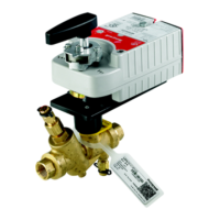
These continuous pilot combination gas controls are
used in gas-fired appliances up to 200 cfh capacity of
natural gas. They include safety shutoff, a manual valve,
one or two automatic operators, a pressure regulator and
a pilot filter. Body pattern is straight-through with 1/2 in.
inlet and 1/2 in. outlet. An ECO connector (part no.
393200-1) with two 1/4 in. quick connect terminals is
available.
See Table 1 for model differences and Table 2 for
temperature ranges and regulator types.
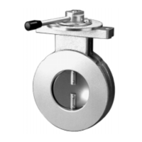
Additional 90° angle and straight flanges are available for
3/8, 1/2, and 3/4 in. pipe. See Table 3 for flange part
numbers. TRADELINE
®
flange kits include one flange
with attached O-ring, four mounting screws, and a 9/64
in. hex wrench.
Controls are factory-set for natural (and manufactured) or
LP gas. Do not attempt to use a control set for natural
(manufactured) gas on LP gas, or a control set for LP on
natural (manufactured) gas.
Controls with standard or slow opening regulators can be
converted from one gas to the other with a conversion kit
(order separately). Order Part No. 393691 to convert
from natural (manufactured) to LP gas; order Part No.
394588 to convert from LP to natural (manufactured)
gas. Controls with step opening regulators cannot be
converted.
CSA Certificate: 112395
Australian Gas Association Certificate: 4752
Table 1. Continuous Pilot Combination Gas Control Models.
Table 2. Model Number Suffix Letter Designation. Table 3. Flange Part Numbers.
a
Elbow (angle) flanges cannot provide right hand inlet
when the ECO connector is used.
NOTE: Flange Kits include one flange with attached
O-ring and four mounting screws. TRADELINE
kits include 9/64 inch hex wrench, as noted.
Model
Voltage
Frequency
Number of
Automatic Operators
Gas Control
Knob Positions
Current
Draw
V8200 24 V/60 Hz One OFF-PILOT-ON 0.30
VR8200 24 V/60 Hz Two OFF-PILOT-ON 0.5
Model No.
Suffix
Letter
Ambient
Temperature
Range
Regulator
Type
A 0° to 175° F (-18° to 79° C) Standard
C 0° to 175° F (-18° to 79° C) Step-opening
H 0° to 175° F (-18° to 79° C) Slow-opening
M -40° to 175° F (-40° to 79° C) Standard
Inlet/Outlet
Pipe Size
Flange
Type
Part No.
Less
Hex
Wrench
With
Hex
Wrench
3/8 in. NPT Straight NA 393690-11
Elbow
a
393690-2 NA
1/2 in. NPT Straight 393690-6 NA
Elbow
a
393690-3 393690-13
3/4 in. NPT Straight 393690-4 NA
Elbow
a
393690-5 393690-15