V8200A,C,H,M AND VR8200A,C,H,M CONTINUOUS PILOT COMBINATION GAS CONTROLS
7 69-0422—03
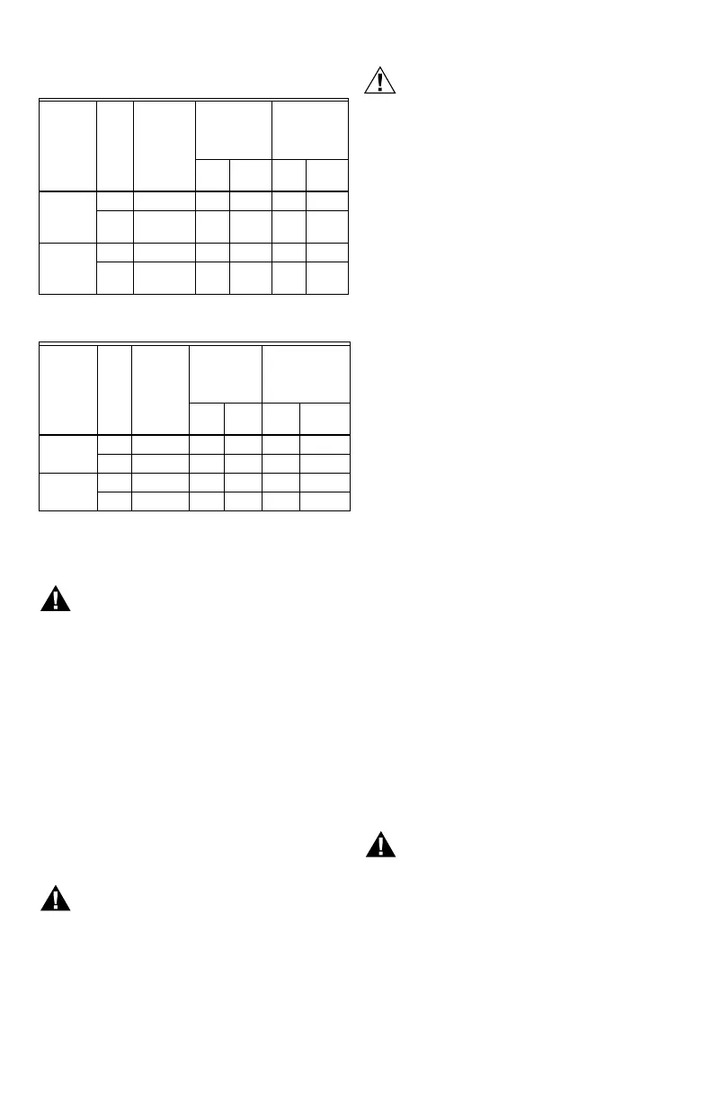
Table 7. Pressure Regulator Specification Pressures
in in. wc.
Table 8. Pressure Regulator Specification Pressures
in kPa.
Check Safety Shutdown
Performance
Fire or Explosion Hazard can cause property
damage, severe injury or death.
Perform the safety shutdown test any time work is
done on a gas system.
1. Place gas control knob in PILOT position. Main
burner should go off and pilot should remain lit.
2. Extinguish pilot flame. Pilot gas flow should
stop within 2-1/2 minutes. Safety shutoff of pilot
gas proves complete shutdown since safety
shutoff valve blocks flow of gas to main burner
and pilot.
3. Relight pilot burner and operate system through
one complete cycle to make sure all controls
operate properly.
SERVICE
Fire or Explosion Hazard can cause property
damage, severe injury or death.
Do not take this control apart; it contains no
replaceable components. Attempted disassembly
or repair may damage the control.
Do not apply jumper across (or short) the
valve coil terminals, even temporarily. Doing
so may burn out the heat anticipator in the
thermostat.
If Pilot Will Not light
1. Make sure the main gas supply valve is open and
the pilot gas supply line is purged of air.
2. Attempt to light pilot following procedure in “Light
Pilot” on page 5.
3. If pilot will not light, check for:
a. closed pilot gas adjustment screw.
b. clogged pilot burner tubing or orifice.
c. gas leak at compression fitting.
If Pilot Goes Out When Reset
Button Is Released
1. Make sure the reset button is held in at least one
minute to allow the thermocouple time to heat.
2. Check pilot flame adjustment, see page 6.
3. Check the connection to the power unit. This is an
electrical connection and must be clean and secure.
4. If pilot still goes out, use a millivoltmeter to measure
the exact open circuit output voltages of the
thermocouple. Compare to acceptable range charts
in the thermocouple specifications. Replace the
thermocouple if voltages are outside the acceptable
range; otherwise, replace the gas control.
If Main Burner Will Not Come On
With Call For Heat
1. Confirm that gas control knob is in the ON position.
2. Adjust thermostat several degrees above room
temperature
3. Using ac voltmeter, measure voltage across
thermostat terminals at gas control.
4. If no voltage is present, check control circuit for
proper operation.
5. If proper control system voltage is present, replace
gas control.
INSTRUCTIONS TO THE
HOMEOWNER
For Your Safety Read Before
Lighting
Fire or Explosion Hazard can cause property
damage, severe injury or death.
Before lighting, smell all around the appliance
area for gas. If the appliance uses LP (bottled)
gas, also be sure to smell next to the floor
because LP gas is heavier than air. If you smell
gas, immediately shut off the manual valve in the
gas piping to the appliance, or, ON LP, AT THE
TANK. Do not try to light any appliance. Don't
touch any electrical switch or use the phone.
LEAVE THE BUILDING and call your gas supplier.
Model
Type
Type
of
Gas
Nominal
Inlet
Pressure
Range
Factory Set
Nominal
Outlet
Pressure
Setting
Range
Step
Full
Rate Step
Full
Rate
Standard,
Slow
NAT 5.0 - 7.0 - 3.5 - 3 - 5
LP 12.0 -
14.0
- 10.0 - 8 - 12
Step NAT 5.0 - 7.0 0.9 3.5 None 3 - 5
LP 12.0 -
14.0
2.2 10.0 None 8 - 12
Model
Type
Type
of
Gas
Nominal
Inlet
Pressure
Range
Factory Set
Nominal
Outlet
Pressure
Setting
Range
Step
Full
Rate Step
Full
Rate
Standard,
Slow
NAT 1.2 - 1.7 - 0.9 - 0.7 - 1.2
LP 2.9 - 3.9 - 2.5 - 2 - 3
Step NAT 1.2 - 1.7 0.2 0.9 None 0.7 - 1.2
LP 2.9 - 3.9 0.5 2.5 None 2 - 3
 Loading...