V8200A,C,H,M AND VR8200A,C,H,M CONTINUOUS PILOT COMBINATION GAS CONTROLS
69-0422—03 6
Turn On Main Burner
Follow instructions provided by appliance manufacturer or
turn thermostat up to call for heat.
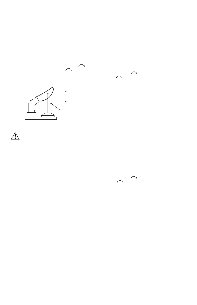
Adjust Pilot Flame
The pilot flame should envelop 3/8 to 1/2 in.
(10 to 13 mm) of the tip of the thermocouple. Refer to
Fig. 9.
1. Remove pilot adjustment cover screw.
Refer to Fig. 4.
2. Turn inner adjustment screw clockwise to
decrease or counterclockwise to increase
pilot flame.
3. Always replace cover screw after adjustment.
Tighten firmly to prevent gas leakage.
Fig. 9. Proper Flame Adjustment.
Check and Adjust Gas Input to Main Burner
1. Do not exceed input rating stamped on
appliance nameplate, or manufacturer's
recommended burner orifice pressure for size
orifice(s) used. Make certain primary air supply
to main burner is properly adjusted for complete
combustion. Follow appliance manufacturer's
instructions.
2. IF CHECKING GAS INPUT BY CLOCKING
GAS METER: Make certain there is no gas flow
through the meter other than to the appliance
being checked. Other appliances must remain
off with their pilots extinguished (or their
consumption must be deducted from the meter
reading). Convert flow rate to Btuh as described
in form 70-2602, Gas Controls Handbook, and
compare to the Btuh input rating on appliance
nameplate.
3. IF CHECKING GAS INPUT WITH
MANOMETER: Make certain gas control is in
PILOT position before removing outlet pressure
tap plug to connect manometer (pressure
gauge). Also turn gas control knob back to
PILOT when removing gauge and replacing
plug. Before removing inlet pressure tap plug,
shut off gas supply at the manual valve in the
gas piping to the appliance or, for LP, at the
tank. Also shut off gas supply before
disconnecting manometer and replacing plug.
Repeat Gas Leak Test at plug with main burner
operating.
Standard Pressure Regulator
1. Check the manifold pressure listed on the appliance
nameplate. Gas control outlet pressure should
match the nameplate.
2. With main burner operating, check gas control flow
rate using the meter clocking method or pressure
using a manometer connected to the outlet
pressure tap on the gas control. Refer to Fig. 4.
3. If necessary, adjust pressure regulator to match
appliance rating. Refer to Table 7 for factory set
nominal outlet pressure and adjustment range.
a. Remove pressure regulator adjustment cap and
screw.
b. Using screwdriver, turn inner adjustment screw
clockwise to increase or counterclockwise
to decrease gas pressure to burner.
c. Always replace cap screw and tighten firmly to
ensure proper operation.
4. If desired outlet pressure or flow rate cannot be
achieved by adjusting the control, check the control
inlet pressure using a manometer at the inlet
pressure tap. If inlet pressure is in normal range
(refer to Table 7), replace the control. Otherwise,
take the necessary steps to provide proper gas
pressure on the control.
Step-Opening and Slow Opening
Pressure Regulator
1. Check the full rate manifold pressure listed on the
appliance nameplate. Gas control full rate outlet
pressure should match this rating.
2. With main burner operating, check the control flow
rate using the meter clocking method or pressure
using a manometer connected to outlet pressure
tap on the control. Refer to Fig. 4.
3. If necessary, adjust pressure regulator to match
appliance rating. Refer to Table 7 for factory set
nominal outlet pressure and adjustment range.
a. Remove pressure regulator adjustment cap
screw.
b. Using screwdriver, turn inner adjustment screw
clockwise to increase or counterclockwise
to decrease gas pressure to burner
c. Always replace cap screw and tighten firmly to
ensure proper operation.
4. If desired outlet pressure or flow rate cannot be
achieved by adjusting the control, check the inlet
pressure using a manometer at inlet pressure tap or
upstream of the gas control. If inlet pressure is in
the normal range (refer to Table 7), replace the
existing control. Otherwise, take the necessary
steps to provide proper gas pressure to the control.
5. STEP-OPENING PRESSURE REGULATORS
ONLY. Carefully check burner lightoff at step
pressure. Make sure burner lights smoothly and
without flashback to orifice. Make sure all ports
remain lit. Cycle burner several times, allowing at
least 30 seconds between cycles for regulator to
resume step function. Repeat after allowing burner
to cool. Readjust full rate outlet pressure if
necessary to improve lightoff characteristics.
M3086B
PROPER FLAME
ADJUSTMENT
3/8 TO 1/2 IN.
(10 TO 13 MM)
THERMOCOUPLE
 Loading...