V8200A,C,H,M AND VR8200A,C,H,M CONTINUOUS PILOT COMBINATION GAS CONTROLS
5 69-0422—03
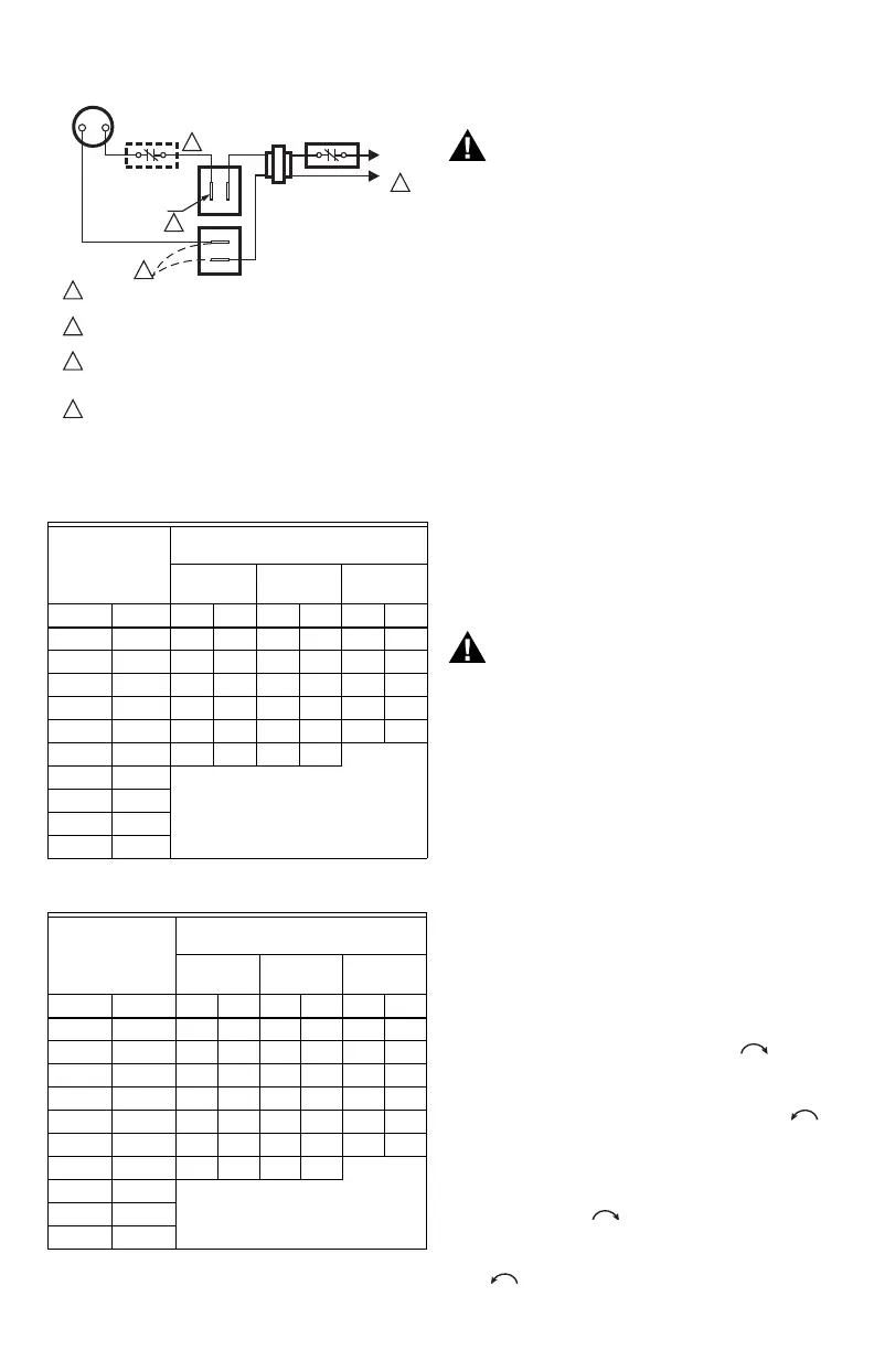
Fig. 8. Wiring Connections.
Table 5. Maximum Length of Supplementary Limit
Leadwires when using Q340A Thermocouple.
Table 6. Maximum Length of Supplementary Limit
Leadwires when using Q309A Thermocouple.
STARTUP AND CHECKOUT
Fire or Explosion Hazard can cause property
damage, severe injury or death.
Do not force the gas control knob on the
appliance. Use only your hand to push down the
reset button or turn the gas control knob. Never
use any tools.
If the knob or reset button will not operate by
hand, or if the reset button stays depressed after it
is released, the control should be replaced by a
qualified service technician.
Gas Control Knob Settings
Gas Control knob settings are as follows:
OFF prevents pilot and main gas flow through the control.
PILOT permits gas to flow to the pilot burner as long as
red knob is held down or thermocouple current is above
the power unit dropout value.
ON permits gas to flow into the control body. Pilot gas is
controlled as in the PILOT position. Main burner gas flow
is controlled by the thermostat and automatic valve
operator(s).
NOTE: Valves are shipped with the gas control knob in
the ON position.
Perform Gas Leak Test
Fire or Explosion Hazard can cause property
damage, severe injury or death.
Check for gas leak with soap and water
solution any time work is done on a gas
module.
Gas Leak Test
1. Paint pipe connections upstream of gas control
with rich soap and water solution. Bubbles
indicate gas leak.
2. If leak is detected, tighten pipe connections.
3. Stand clear of main burner while lighting to
prevent injury caused from hidden leaks which
could cause flashback in the appliance
vestibule. Light main burner.
4. With main burner in operation, paint pipe joints
(including adapters) and control inlet and outlet
with rich soap and water solution.
5. If another leak is detected, tighten adapter
screws, joints, and pipe connections.
6. Replace part if leak can't be stopped.
Light Pilot
1. Rotate the gas control knob clockwise to OFF.
Wait five minutes to allow any unburned gas to
dissipate. Sniff around the appliance near the floor.
Don't relight if you smell gas.
2. Rotate the gas control knob counterclockwise
to PILOT. Push down and hold the red reset button
while you light pilot burner according to appliance
manufacturer's instructions.
3. After about one minute, release reset button. Pilot
should remain lit. If it goes out, turn gas control
knob clockwise to OFF. To relight, repeat
steps 1-3.
4. After pilot remains lit when red reset button is
released, turn gas control knob counterclockwise
to ON.
Thermocouple
Length
Maximum Leadwires Length X 2
(wires)
AWG
No. 14
AWG
No. 16
AWG
No. 18
Inches Meters in. m in. m in. m
12 0.3 41 1.0 26 0.7 16 0.4
18 0.5 35 0.9 22 0.6 13 0.3
24 0.6 29 0.7 18 0.5 11 0.3
30 0.8 23 0.6 15 0.4 9 0.2
36 0.9 17 0.4 11 0.3 6 0.2
40 1.0 13 0.3 8 0.2
48 1.2
DO NOT USE
54 1.4
60 1.5
72 1.8
Thermocouple
Length
Maximum Leadwires Length X 2
(wires)
AWG
No. 14
AWG
No. 16
AWG
No. 18
Inches Meters in. m in. m in. m
12 0.3 47 1.2 30 0.8 18 0.5
18 0.5 41 1.0 26 0.7 16 0.4
24 0.6 35 0.9 22 0.6 14 0.4
30 0.8 29 0.8 18 0.5 11 0.3
36 0.9 23 0.6 15 0.4 9 0.2
40 1.0 19 0.5 12 0.3 7 0.2
48 1.2 11 0.3 7 0.2
54 1.4
DO NOT USE60 1.5
72 1.8
L1
(HOT)
L2
1
24V
THERMOSTAT
OPTIONAL
CONVENIENCE
TERMINALS
TH/TR
TH
TR
GAS CONTROL
TERMINALS
HIGH LIMIT
CONTROLLER
POWER SUPPLY. PROVIDE DISCONNECT MEANS AND OVERLOAD
PROTECTION AS REQUIRED.
DO NOT JUMPER THESE TERMINALS. THIS SHORTS VALVE COIL
AND CAN BURN OUT ANTICIPATOR IN THERMOSTAT.
CONVENIENCE TERMINALS SERVE ONLY AS A TIE POINT.
THEY ARE NOT INTERNALLY WIRED TO THE CONTROL CIRCUIT
OR TO GROUND.
OPTIONAL HIGH LIMIT.
1
2
3
4
2
3
4
M2915A
 Loading...