162 43-TV-25-30 Iss.6 GLO Aug 07 UK
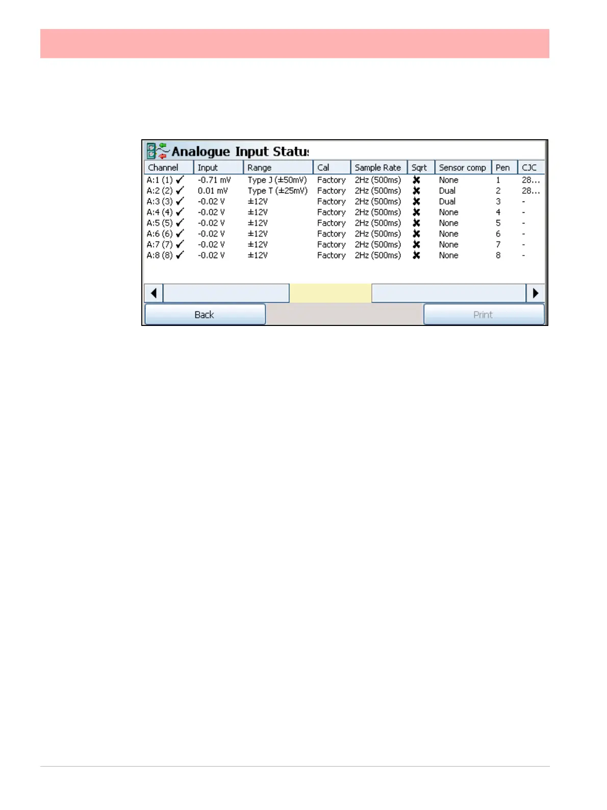
Analogue In Status
(Main Menu > Status > Diagnostics > Hardware > Analogue In)
• Channel - Displays the Slot position eg. A, B, or C, D, E, F, the Analogue Input number
and the system channel position. This will show a tick if this channel is enabled.
• Input - Displays the current Analogue Input reading for this channel. *See “Thermo-
couple Active Burnout Status” on page 163.
• Range - Displays the current Range Type set for this channel, eg. +/-12V
• Calibration - Displays the type of calibration for this channel either Factory or User Cal
• Sample Rate - Displays the current Sample rate for this channel.
• SQRT - If ticked the square root extract is enabled on this channel to linearise a non-lin-
ear input.
• Sensor Comp - This will display if any type of sensor compensation applied to this
channel.
• Pen - Displays which Pen scale is being used to display this analogue input.
• CJC - Only for Thermocouple inputs. Displays the final adjusted value of a Cold Junc-
tion Calibration on this channel in degrees C.
Go Back to return to the previous screen or select Print to print the screen.
*Displayed in the Input column may also be the Thermocouple Active burnout status
 Loading...