EXCEL 500/600 - INSTALLATION INSTRUCTIONS
EN1R-1047GE51 R0913 8
3. Code the terminal block (see section "Coding the
Terminal Block (not XCL5010)" on page 6).
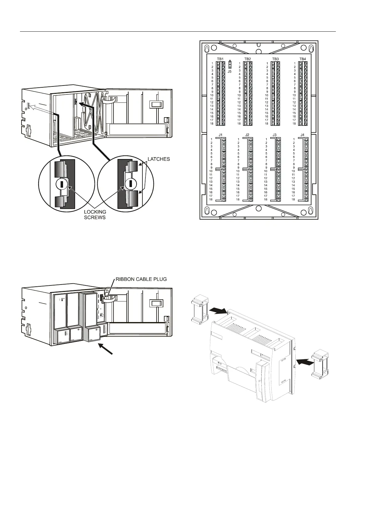
4. Make sure that the locking screws are positioned as
shown in Fig. 13.
5. Plug in the enclosure.
Fig. 13. Housing locking screws and latches
6. Shift latches inwards until the housing is released.
7. Set the module addresses (see section "Setting the
Module Address (not XCL5010)" on page 7).
8. Insert the modules.
Fig. 14. Modules and ribbon cable
9. Plug the ribbon cable onto the CPU module.
10. Close the cover.
Extended wiring base (wall-mounting, only; US, only):
As an alternative to the base plate, an extended wiring base
may be used. This is available for the U.S. market, only, and
can be ordered without cover plate (OS No. 14507274-001)
or with cover plate (OS No. 14507274-002).
Fig. 15. Excel 500/600 extended wiring base
Using the extended wiring base the I/O terminals are
accessible at run-time.
XCL5010
1. Attach the DIN rail mounting clips to the housing.
2. Mount the controller on the DIN rail.
Fig. 16. Mounting XCL5010 on DIN rail (a)
 Loading...


