SERVICING & DISMANTLING INSTRUCTIONS
Important Notes
for
Guidance:
Before commencing any
work
refer to the Safety Notes at the beginning
of
this manual.
A.
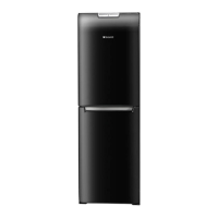
Removing the Fridge Door
1.
Remove the top hinge blanking plug.
2.
While supporting the fridge door, unscrew and remove the top hinge pin and lift the door from the
centre hinge.
3.
Unclip the upper hinge surround strip from the door to reveal the magnet(s)
on
the reverse side.
B.
Removing the Freezer Door
1.
Remove the fridge door as
in
A 1 to A2.
2.
While supporting the freezer door, remove the centre hinge assembly.
3.
Lift the freezer door enough to release it from the lower hinge pin.
C.
Control Panel (housing the Control Module)
1.
Remove the fridge door
as
in
A 1 & A2.
2.
Unclip and remove the top hinge cover and the left hand blanking cover
by
sharply pressing hard just
left of the centre of each cover.
3.
Remove the two screws securing the control panel to the cabinet.
4.
Pull the control panel forward enough to gain access to the control module and wiring harness.
5.
Release the wiring from the control module.
D.
Control Module
1.
Remove the fridge door and control panel
as
in
C 1
to
CS.
2.
Set the temperature control knob to the OFF position before unclipping the control module from the
panel.
NOTE: -
On
reassembly align the control knob to the potentiometer mounted
on
the module.
When assembled check that the temperature selector can rotate through
all
its settings.
E.
Door Seals (replaceable)
NOTE: - There
is
a moulding at the rear of the door seal that locates into a groove
in
the door liner
to secure
it.
1.
To replace, ease the seal away from the door liner starting at the middle of one of the sides then work
around the door to release completely. If the seal
is
a tight fit into the liner, the liner must
be
supported
to prevent any damage.
F.
Interior Lamps
1.
Unclip the lamp cover.
2.
Unscrew the relevant lamp; the replacement lamp must be of the same rating
as
the power range
indicated
on
the cover (10W).
G.
Multi-Flow Unit
1.
Remove the contents, food and furniture.
2.
Remove the plastic cover from the interior lamp housing.
3.
Unscrew the screws at base of multiflow unit and from the inside of the lamp holder.
4.
Pull the base of the multi-flow unit towards you while simultaneously sliding it downwards releasing
it from the top locating lugs.
5.
Disconnect the lamp holder wiring from the connector block.
6.
Replace seals as necessary
to
ensure good sealing.
7.
When reassembling, ensure the wiring
is
not able
to
foul the damper or
be
trapped by the duct
moulding.
NOTE: - The phial from the baffle thermostat needs to be positioned into the exhaust (return) duct.
18
VVPL00003242_0018