Page 17
Page 17
Page 17
IMPORTANT: Should you ever find the need to move or relocate your Hot Spring
®
spa, it is essential that you understand and apply these
installation requirements. Your Hot Spring spa has been carefully engineered to provide maximum safety against electric shock. Remember,
connecting the spa to an improperly wired circuit will negate many of its safety features.
ADVANTAGE TO HAVING YOUR SPA CONVERTED
Inthe115voltconfiguration,eithertheheater,orthejetpumpcanoperate,buttheycan’tworkatthesametime.Ina115voltsystem,aslongas
the jet pump is activated, the heater will not turn on. On the other hand, when the spa is converted to operate in the 230 volt configuration, the
heater and jet pump can operate simultaneously.
The heater will operate at 1500 watts when the spa is configured as a 115 volt cord-and-plug connected model, and at 6000 watts when the spa
is configured as a 230 volt converted model heating your spa water faster.
230 VOLT BOLT
™
MODEL CONVERSION INSTRUCTIONS
Hot Spring
®
spas must be wired in accordance with all applicable local electrical codes. All electrical work should be done by an experienced,
licensed electrician. We recommend the use of appropriate electrical conduit, fittings, and wire for all circuits.
Refer to the following instructions to convert from 115 volt to 230 volt
IMPORTANT: Converting the spa to 230 volt operation will require both an authorized
Hot Spring
service agent and a qualified electrician.
Required Part: A Subpanel (230 volt Convertable) available from your Hot Spring dealer.
1. Disconnect the power cord from the house receptacle.
2. Remove the screws from the center front door panel, lift panel up then pull bottom of panel
away from spa and remove. Repeat for front side door panels if necessary.
3. Remove the screws on the front of the spa control box.
4. Open the control box cover.
5. Identify Terminal block located in the lower left-hand corner inside the control box.
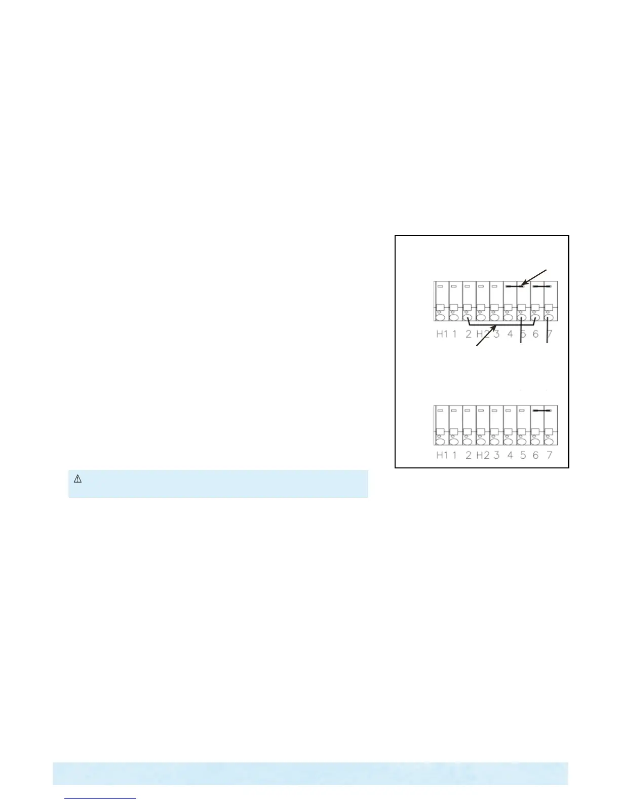
6. Refer to illustration, Step 1. Remove the 2 pin jumper attached to terminals
4 and 5.
7. Refer to illustration, Step 1. Remove the wire jumper from terminals 2, and 6.
8. Refer to illustration, Step 2. Remove the power cord wires from 5, 7 and GRD (not
illustrated).
9. Unscrew the power cord strain relief and remove the power cord from the access hole in
the control box.
WARNING: Do not allow pliers to contact any electronic components inside the
control box.
Converting from 115 volts to 230 volts changes the voltage supplied to the
heater from 115-volts to 230 volts. The jet pump will continue to
operate at 115 volts.
Have your licensed electrician wire subpanel from a 50A Main Service, then from subpanel into the spa's control box using the following illustration or
use the wire diagram on the inside of the control box lid.
IMPORTANT: The subpanel must be placed in sight of the spa, at a minimum distance of 5 feet away.
Remove the Terminal Block Power Jumper
using needlenose pliers From terminal 4-5.
Remove wire jumper from 2 & 6.
Remove the three power cord wires from
terminal block 5,7 and GRD. Leave Terminal
Block Power Jumper 6-7 in place.
Step 1
Step 2
Electrical Requirements