ELEcTRIcAL REqUIREMENTS
ANd pREcAUTIONS
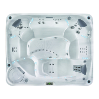
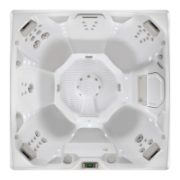
Your Hot Spring
®
spa has been carefully designed to give you maximum safety against electric shock. Connecting the spa to an improperly wired
circuitwillnegatemanyofthespa’ssafetyfeatures.Improperwiringmayalsocauseelectrocution,riskoffire,andotherrisksofinjuries.Please
read and follow the electrical installation requirements and instructions for your specific spa model completely!
SERVICE NOTE: The Hot Spring spa is equipped with a power indicator which, in addition to showing the spa has power to it, has a diagnostic
function as well. It will begin blinking if the heater high-limit thermostat has tripped. If the power indicator light is blinking, follow the instructions in the
Troubleshooting section to identify and correct the cause. The power indicator will stop blinking once the problem has been corrected.
230 VOlT PERMANENTlY CONNECTEd MOdElS
(glEAM
™
, PUlSE
®
, FlAIR
®
& glOW
®
MOdElS)
ELECTRICAL REQUIREMENTS
HOT SPRINGSPAMUSTBEWIREDINACCORDANCEWITHALLAPPLICABLELOCALELECTRICALCODES.ALLELECTRICALWORK
SHOULD BE DONE BY AN EXPERIENCED, LICENSED ELECTRICIAN. WE RECOMMEND THE USE OF APPROPRIATE ELECTRICAL
CONDUIT, FITTINGS, AND WIRE FOR ALL CIRCUITS.
An electrical subpanel containing two GFCI breakers is included with each 230 volt spa. We recommend that this subpanel be used to supply
power and protect the spa.
This subpanel requires a 50 amp, single phase, 230 volt, four wire service (two line, one neutral, one ground). The grounding conductor must not
be less than #10 AWG. Refer to local codes and to NEC 250-122 (table).]
The Gleam will require an additional 20 amp breaker in order to operate the heater and jet pump 3 at the same time. Without the additional 20 amp
breaker, the heater will NOT operate while jet pump 3 is on.
Mount the subpanel in the vicinity of the spa, but not closer than five feet away, in accordance with all local codes. (N.E.C. 680-38 to 41-A-3).
INSTALLATION INSTRUCTIONS
1. To connect the electrical service, first remove center front door panel (same side as the control panel, see step 2).
2. Remove the screws from the center front door panel, lift bottom of panel away from spa, lower and remove. Repeat for front side door panels if
necessary.
3. Locate the IQ 2020
®
spa control box. Loosen the screws on the front of the control box. Remove the screws and the control box cover.
4. Route the electrical service from the subpanel into the spa equipment compartment using the cut out in the frame below the door.
NOTE: The subpanel must be placed in sight of the spa, at a minimum distance of five feet away.
5. Connect the supply conduit to the bottom of the IQ 2020 spa control box, using a 3/4” liquid-tight, flex conduit fittings.
WIRING CONNECTIONS
1. Identify the TB-1 terminal block, located inside the control box at the lower left-hand corner.
2. Connect the #12 AWG, BLUE wire, from the subpanel 20 amp breaker, terminal L1 to TB-1, terminal 2.
3. Connect the #12 AWG, RED wire, from the subpanel 20 amp breaker, terminal L2 to TB-1, terminal 4.
NOTE: The WHITE neutral wire must be attached to the LOAD neutral on the 230 volt, 30 amp breaker (not to the neutral bus bar in the subpanel).
The WHITE neutral wire coming from the breaker itself is already connected to the neutral bus bar.
4. Connect the #10 AWG, BLUE wire, from the subpanel 30 amp breaker, terminal L1 to TB-1, terminal 5.
5. Connect the #10 AWG, RED wire, from the subpanel 30 amp breaker, terminal L2 to TB-1, terminal 6.
6. Connect the #10 AWG, WHITE wire, from the subpanel 30 amp breaker, terminal N (load neutral) to TB-1, terminal 7.
7. Connect the #10 AWG, GREEN wire, from the subpanel GROUND bar to TB-1, system ground terminal.
8. Using the pressure wire connector provided on the outside of the control box, bond the spa to all exposed metal equipment or fixtures,
handrails, and the concrete pad (if applicable) per N.E.C. and local codes.
9. Replace the control box cover and securely tighten the fastening screws. Close and secure the equipment compartment panel as follows:
•Placetopofpaneldirectlybelowbartopagainsttheframeofthespa.
•Slidepanelupwarduntilscrewholeslineup.Insertandtightenthescrews.
Page 12
Page 12
Electrical Requirements