8
3 Structure
A functional rotary heat exchanger consists of the wheel, the
casing and the drive.
3.1 Wheel
Storage mass
A corrugated and a smooth metal foil are wound together
as the storage mass. This forms triangular, axial ducts. The
material is 60 µm thick.
The surface treatment also depends on the use; there are
3 series:
■ Series A: condensation wheel, consisting of high-quality
aluminium.
■ Series E: enthalpy wheel, consisting of aluminium with
enthalpic coating.
■ Series S: sorption wheel, consisting of an aluminium
substrate foil coated with a sorption substance (e.g. silica
gel) for humidity transmission. This transmits humidity in
the form of a gas without condensation.
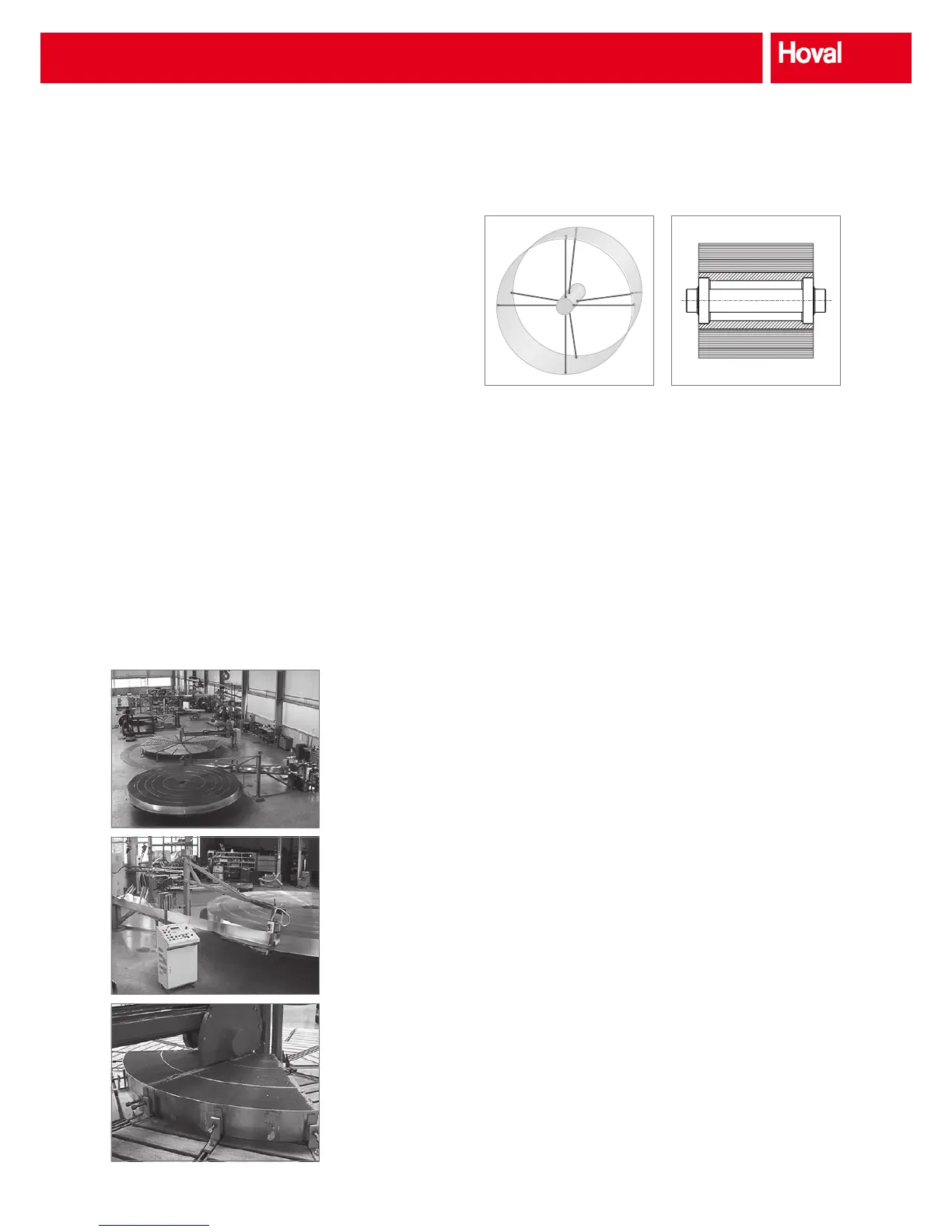
Fig. 9: A corrugated and a
smooth metal foil are wound
around each other.
Fig. 10: Production on state-
of-the-art machines ensures
consistently high quality.
Fig. 11: Large wheels are cut
into several segments.
Design
The depth of the wheel is 200 mm. The wheel is stabilised by
double spokes, screwed (and welded) to the hub and welded
to the wheel mantle (see Fig. 12). This guarantees a long
service life.
For stability and performance large-diameter wheels must be
made in a segmented design. The diameter of the wheel can
be freely selected in 10-mm steps.
The outside of the wheel is held together by an aluminium
jacket plate (welded). This guarantees uninterrupted radial
runout and enables maximum usage of the wheel surface.
Hub with inner bearing
The hub, whose size depends on the wheel diameter, is
xed to the axle with 2 internal ball bearings. It is fastened
to the crossbars of the casing. This design has the following
advantages:
■ The internal bearings are protected against contamination
and require little space.
■ The axial lock with circlips makes installation and removal
quick and simple.
■ Both bearings are integrated into the hub, i.e. in the
same component. This ensures that they mesh together
perfectly (in contrast to external bearings). This does not
reduce the service life of the bearings.
■ The position of the axle, hub and wheel is precisely xed
by the fastening of the internal ball bearings by the hub
and the circlips.
■ The xed axles connects the two crossbars of the casing.
This greatly increases its stability.
Fig. 12: The wheel is permanently stabi-
lised by internal welded double spokes.
Fig. 13: Hub with long-life, permanently
lubricated inner bearing
Structure



 To Next Page