12
4.2 Control unit
Structure
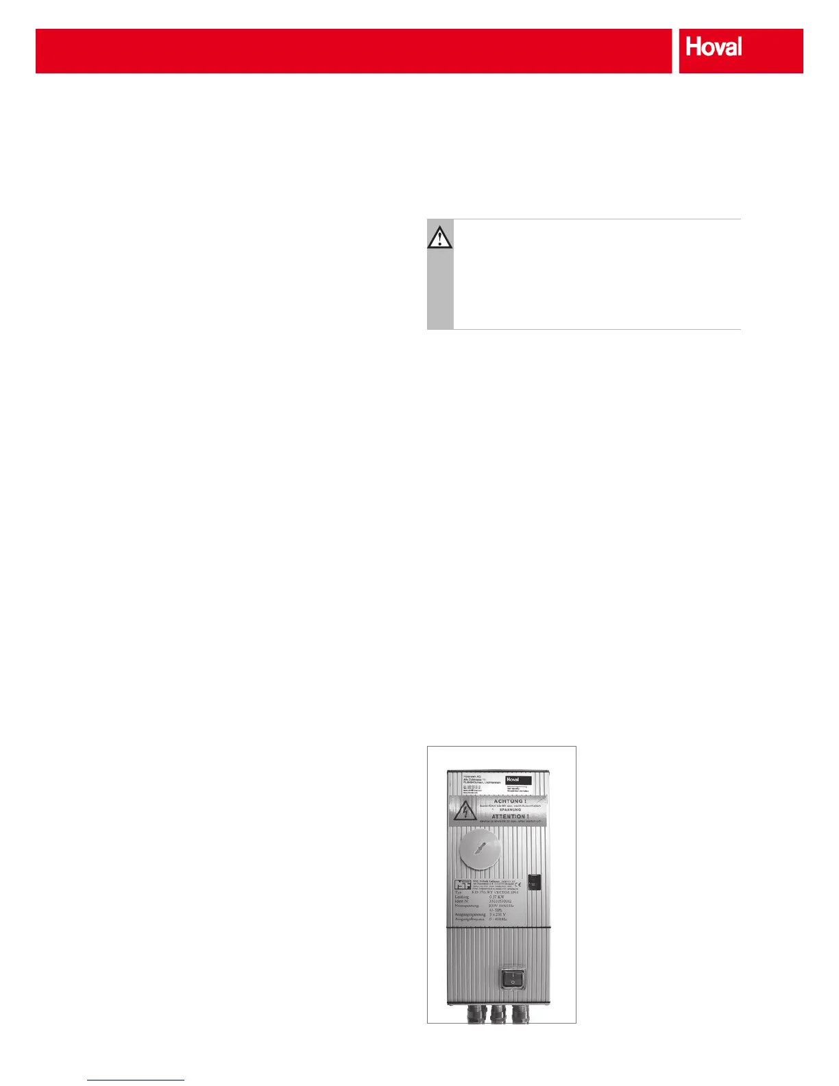
A frequency converter with a modular design is used as the
control unit; it can adjust the speed of three-phase motors
innitely. Protection rating IP 54 is required for installation in
the ventilation unit. The power unit is protected from under-
voltage, overvoltage or non-approved converter temperature.
The aluminium casing and the standard input and output
lters increase the immunity to interference. Error messages
can be read out directly at a ashing LED.
The control unit is delivered ready for operation with the
factory-set parameters. Various settings can be changed with
an optionally available operating unit.
Function
■ The control unit can be used for condensation, enthalpy
and sorption wheels that require speed control. All
standard control signals are accepted.
■ A quadratic (standard) or linear implementation of the
setpoint into the rotary eld frequency based on the
maximum frequency of the selected parameter set is
used.
■ As soon as the input signal is below the dened threshold
value, the wheel stops rotating. After an adjustable holding
time intermittent operation is started and the wheel rotates
at the dened speed for a few seconds.
■ An inductive sensor can be connected for speed moni-
toring (option D).
■ Readiness for operation and any fault messages can be
output via a relay.
System design
■ The control unit is not designed for outside installation.
■ The control unit is normally installed in the side wall of the
casing.
■ The normal installation position is vertical. Sufcient venti-
lation for heat dissipation is essential.
Fig. 17: Control unit R
Installation
Caution
All work for transport, installation and commissioning
as well as maintenance is conducted by qualied
technicians (note IEC 364 and VENELEC HD 384 or
DIN VDE 0100 and IEC Report 664 or DIN VDE 0110
and national occupational health and safety regula-
tions or VGB 4).
Qualied technicians as dened by the basic safety instruc-
tions are persons who are familiar with the setup, installation,
commissioning and operation of the product and are appro-
priately qualied for their activities (dened in IEC 364 or DIN
VDE 0105).
Commissioning
■ Before commissioning the control unit the rotary heat
exchanger must be operating correctly.
■ The direction of rotation of the wheel can be changed by
reversing 2 phases of the motor.
■ A green LED lights when the unit is operating without
faults.
■ Causes of faults are displayed on the control unit.
Options



 To Next Page