21
8 Transport and installation
The following checks must be performed before installation:
■ Has the rotary heat exchanger been damaged during
transport (visual inspection of casing and wheel)?
■ Has the correct model been supplied (type, series, size,
options)?
■ How must the exchanger be mounted (purge sector)?
(Note labels!)
8.1 Transport
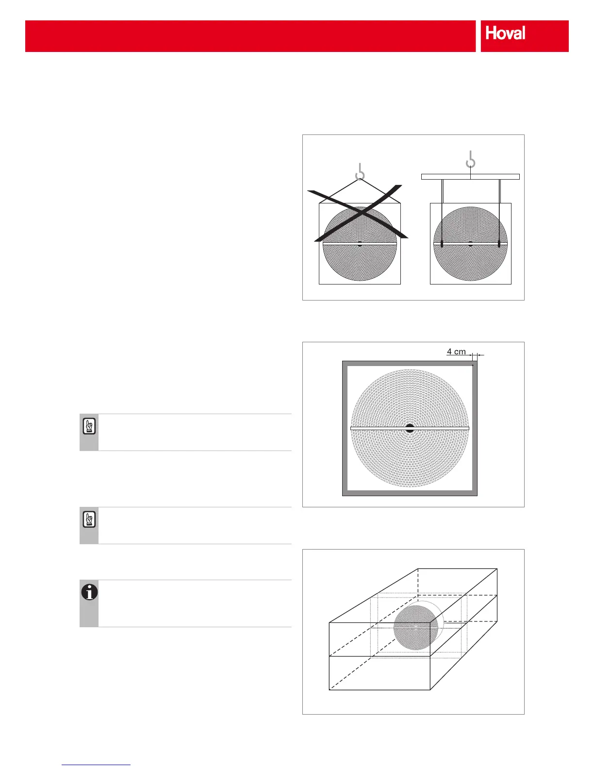
■ The wheel should always be vertical during transport.
■ The rotary heat exchanger should be attached to the
crossbars of the casing. The pulling direction should be
vertical to prevent damage.
■ The following general items are applicable: Do not lift the
exchanger at a single point but always suspend it by a
crane beam (Fig. 20).
8.2 Mechanical installation
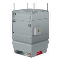
■ The casing for duct connection can be bolted or riveted at
the face area up to 4 cm from the outer frame (Fig. 21).
Caution
The wheel casing cannot take any additional load
(e.g. ducts).
■ When installing the wheel in a ventilation unit, the casing
should be reasonably adapted to the unit size (Fig. 22).
■ If necessary, bafe plates can be installed to adapt the
casing to the unit cross-section.
Caution
Ensure that the wheel is not drilled or blocked and
the sealings are not damaged during installation.
■ Hoval rotary heat exchangers are designed for vertical
installation (max. tilt 20°).
Notice
Rotary heat exchangers for horizontal installation
are available on request. In this case the casing
must be supported at the bearings.
■ After installation check that the wheel runs smoothly.
8.3 Installation of sensors
If, for example, temperature sensors are installed, the func-
tion of the unit must not be affected.
Fig. 20: Recommended attachment
Fig. 21: Drill area
Fig. 22: Casing dimensions adjusted for unit
Transport and installation