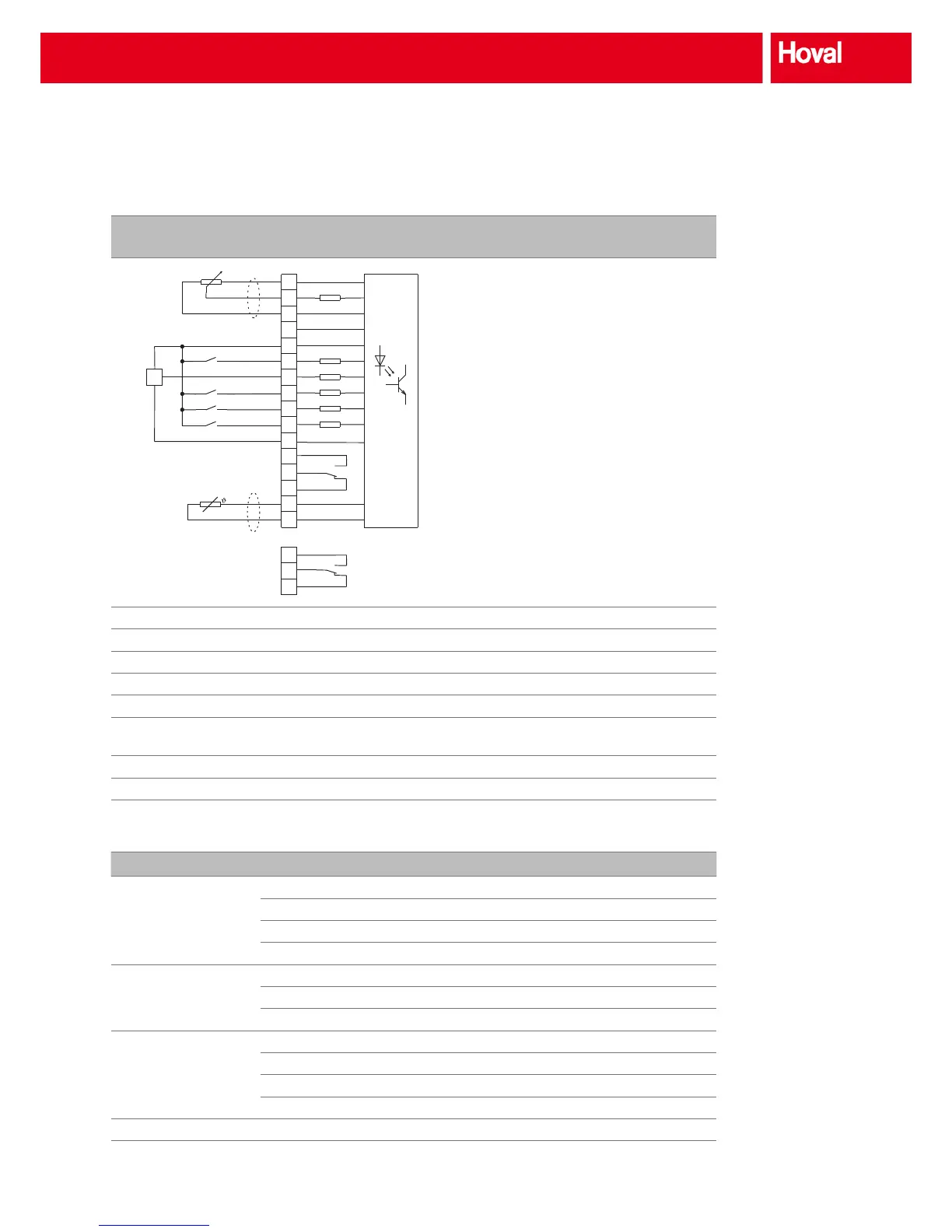
+10 V reference voltage
Analogue setpoint input
GND (analogue)
Analogue output
+15 V (max. 100 mA)
Start clockwise
External sensor
Priority speed
Parameter set switching
Release
GND (digital)
Relay output 1 (normally open contact)
Relay output 1 (changeover contact)
Relay output 1 (normally closed contact)
PTC motor temperature monitoring
PTC motor temperature monitoring
Relay output 2 (normally open contact)
Relay output 2 (changeover contact)
Relay output 2 (normally closed contact)
Terminals 1, 2, 3 Connection of control signal
Terminals 5, 7, 11 Connection of inductive sensor for speed monitoring
Terminal 6 Start of wheel (terminal 10 must be under power)
Terminal 9 not under power Sorption wheel operating mode
Terminal 9 under power Condensation/enthalpy wheel operating mode
Terminal 10 Reset-function by short-term voltage cut-off,
acknowledgements of faults
Terminals 15, 16 Connection of thermal contact from motor
Terminals 17, 18, 19 Potential-free output for output of faults via relay
Table 3: Circuit diagram of control inputs for control units
R/370 R/750
Output motor-side Max. motor power kW 0.37 0.75
Nominal output current A 2.2 4.0
Max. output voltage V 3 x 230 3 x 230
Output frequency Hz 0..500 0..500
Mains input Rated voltage V 230 230
Mains frequency Hz 50/60 50/60
Fuses A T 6 8
General data Protection rating IP 54 IP 54
Ambient temperature °C 0..40 0..40
Air humidity % 20..90 20..90
Power dissipation W 35 45
Dimensions H x W x D mm 282 x 112 x 70 282 x 112 x 70
Table 4: Technical data for the control units
Options



 To Next Page