134 214 283 / 00
ASSEMBLY
2.5 Mounting the cladding and boiler control Max-3 plus (1000,1250)
7. Fix bolts (7, Fig. 13) with hexagon nuts and U-washers to the door and then mount insulating mat (7a/7b) and door cladding (7c).
8. Attach shield plate (8, Fig. 15) to the front of the boiler.
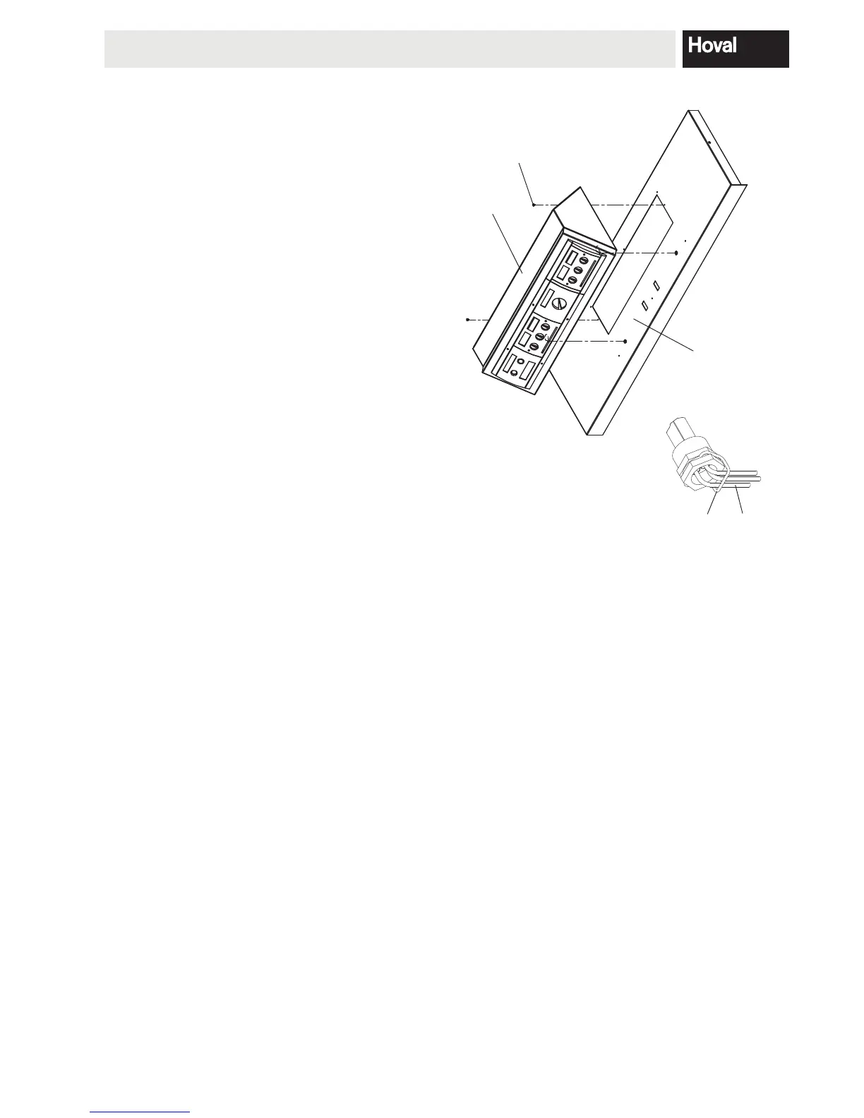
9. Remove the control box cover (9, Fig. 13). Attach the control box (9a, Fig. 11) with the cut-out for special screws to the cladding cover (9b) and secure with 2
self-tapping screws and serrated lock washers (9c) ø 3.8 x 6.5mm.
10. Install burner connector plug (10, Fig. 13) in the left or right side wall (Observe boiler door opening side, see point , 4.6.1 on page 28). Attach 2 C-clips (10a)
to the top of each side wall. Mount the front side walls (10b/10c) at the bottom to the pins mounted to the boiler plinth rail and route burner cable (10d) upwards
11. Pull capillaries with immersion sensors (11, Fig. 12) as far as the stop in the immersion sleeve (11a, Fig. 13) and secure with retaining spring (11b, Fig. 12).
Attention: The capillaries must not be kinked!
12. Fix the control box cover (9, Fig. 13) with self-tapping screws ø 3,5 x 6,5mm and serrated lock washers.
13. Mount the rear side walls (13/13a) at the bottom to the pins mounted to the boiler plinth rail (Fig. 14).
14. Attach the bottom rear wall (14, Fig. 13) to the special screws in the rear side walls.
15. Place 4 insulating mats (15) left and right in longitudinal direction (to prevent vertical air circulation).
16. Position cladding cover (16).
17. Attach the top rear wall (17) to the bottom rear wall (14) and attach the cladding cover (16)
to the special screws on the top rear wall (17).
18. Mount the middle side walls (18/18a) at the bottom to the pins mounted to the
boiler plinth rail.
19. Position cladding cover (19/19a).
20. Fix all the cladding covers (16/19/19a) with self-tapping screws and replace
the cleaning cover.
21. Fix lead-through (21).
22.
Fig. 11
Fig. 12
11b
11
9a
9c
9b
Affix rating plate and manual storage case to the side.
to the control (cable routing according to Fig. 13). Mount cladding cover (9b, Fig. 11) and fix with self-tapping screws. Plug in the burner cable (10e, Fig. 13).

 Loading...