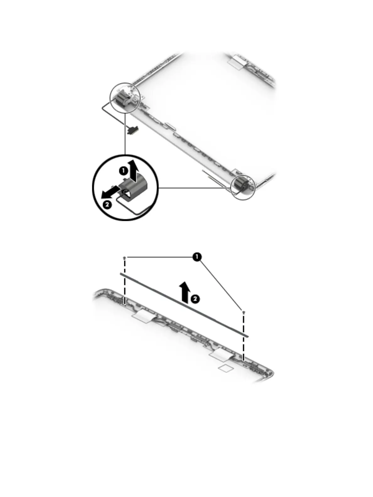
b. Remove the caps from the hinges (2).
c. Remove the two Phillips PM2.0×3.0 screws (1), and then lift the top display hinge (2) o the
display.
d. Remove the three broadhead Phillips PM2.5×3.0 screws (1) and the PM2.0×3.0 screw (2) that
secure each hinge to the display enclosure.
Component replacement procedures 71