Solid-state drive bracket and connector board
Table 6-6 Solid-state drive bracket, connector board, and cable descriptions and part numbers
Description Spare part number
Solid-state drive bracket L22535-001
Solid-state drive connector board L22542-001
Solid-state drive cable L22527-001
Before removing the solid-state drive bracket and connector board, follow these steps:
1. Prepare the computer for disassembly (Preparation for disassembly on page 32).
2. Remove the optical drive (see Optical drive on page 33).
3. Remove the bottom cover (see Bottom cover on page 37).
4. Remove the battery (see Battery on page 40).
5. Remove the solid-state drive (see Solid-state drive on page 46).
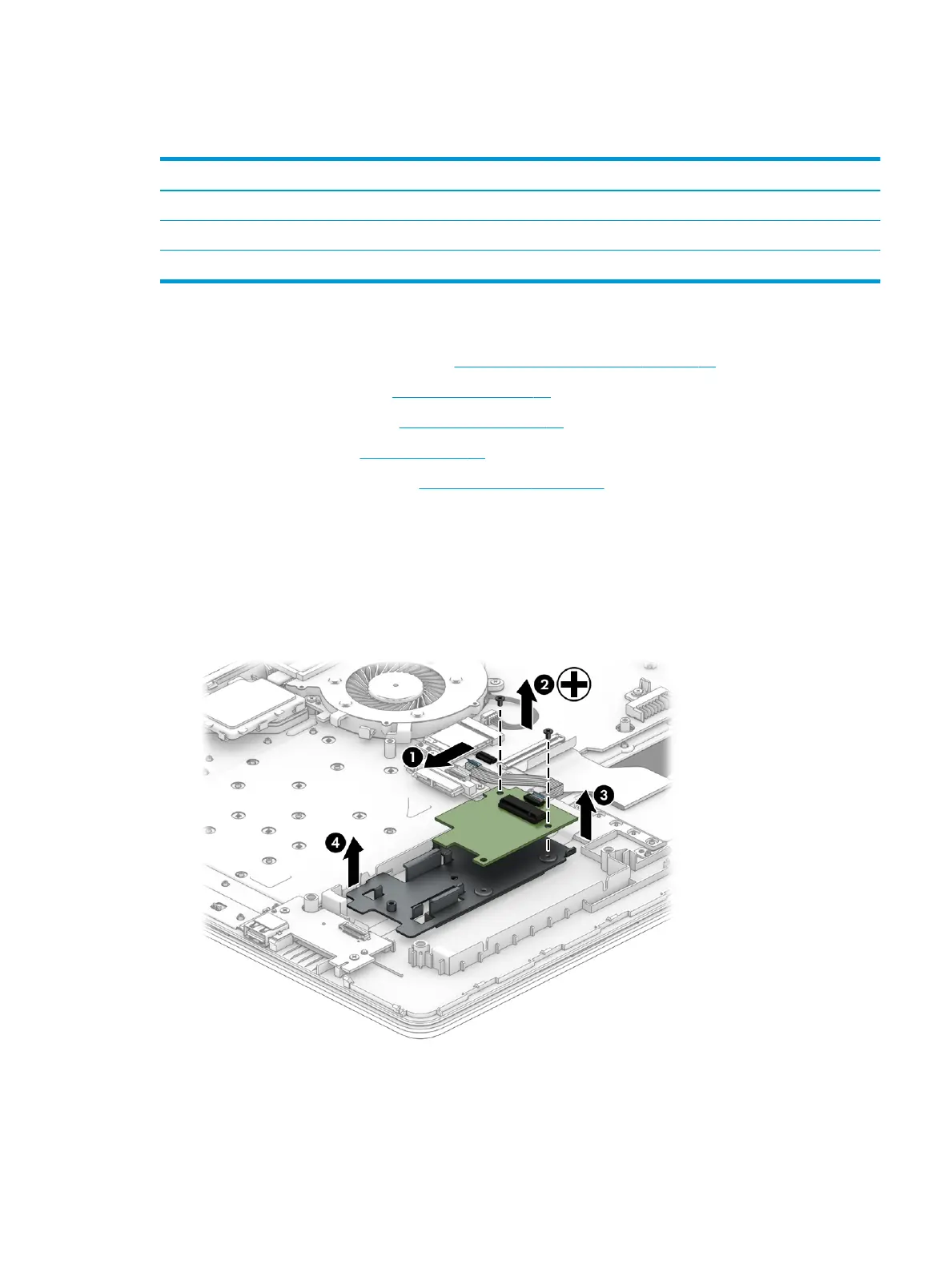
Remove the solid-state drive bracket and connector board:
1. Disconnect the cable from the system board ZIF connector (1).
2. Remove the two Phillips M2.0 × 3.0 screws (2) that secure the board and bracket to the computer.
3. Remove the board from the computer (3).
4. Remove the bracket from the computer (4).
Reverse this procedure to install the solid-state drive bracket and connector board.
Component replacement procedures 47
 Loading...