This document serves as a comprehensive Maintenance and Service Guide for the HP 32s model monitor, providing essential information for trained service personnel. It outlines procedures for spare parts, removal and replacement of components, diagnostic tests, and problem troubleshooting.
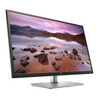
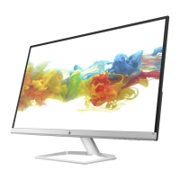
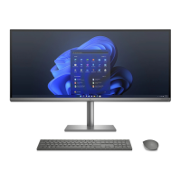
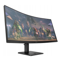
The HP 32s monitor is a liquid crystal display (LCD) featuring an active matrix, thin-film transistor (ADS) screen designed for various viewing needs. Its primary function is to display visual content from a connected computer system or other video sources. The monitor supports a large diagonal display, offering an immersive viewing experience. It is capable of a maximum graphics resolution of 1920 x 1080 at 60Hz, with full-screen support for lower resolutions, ensuring compatibility with a wide range of input signals.
For connectivity, the monitor includes both VGA analog and HDMI digital signal inputs, providing flexibility for connecting to different devices. The HDMI input also supports HDCP (High-bandwidth Digital Content Protection) copy protection, ensuring secure playback of protected digital content.
The monitor is designed for user convenience with several usage features. It offers easy viewing from various positions, whether sitting or standing, or when moving from one side of the monitor to the other, thanks to its wide viewing angles inherent to ADS technology. Tilt adjustment is available, allowing users to customize the screen angle for optimal comfort and reduced glare. The monitor also features a removable base, which can be useful for mounting the display on a wall or an alternative stand using a VESA-compatible mount (though the VESA bracket is a separate component). For security, a security lock slot is integrated, allowing the use of a locking security cable (sold separately) to deter theft.
Plug and Play capability, if supported by the connected computer system, simplifies setup by automatically configuring the monitor without requiring manual driver installation. The On-Screen Display (OSD) provides intuitive adjustments in several languages, enabling easy setup and screen optimization for various viewing preferences. These adjustments include controls for brightness, contrast, color settings, and input selection. The OSD menu is accessed via a dedicated Menu button, and Function buttons allow navigation and quick selection of commonly used operations, which can be reconfigured by the user. A Power button is present for turning the monitor on and off. An energy saver feature is incorporated to meet requirements for reduced power consumption, contributing to energy efficiency.
Maintenance features are detailed for professional service technicians. The guide emphasizes important safety information and precautions, stressing that only trained service personnel familiar with the product should perform maintenance. It highlights the importance of a dry and clean working environment, proper safety devices, and approved tools. A critical safety instruction is to always disconnect the power cord before opening the monitor to prevent component damage and electrical shock. The document also warns about electrostatic discharge (ESD) sensitivity of electrical components and provides guidelines for handling such parts. For products containing batteries, specific warnings against disassembly or exposure to high temperatures are given, along with a reminder to refer to government requirements for battery recycling and disposal.
The guide outlines two levels of service: Level 1 for cosmetic/appearance/alignment service and Level 2 for circuit board or standard parts replacement. It specifies that repairs must be performed by professional service technicians in a repair center, not by end-users. A key precaution for servicing is noting that the primary side of the power board is a high voltage area. The monitor meets RoHS (Restriction of Hazardous Substance) requirements, mandating the use of lead-free solder wire for soldering. When replacing capacitors, technicians are instructed to match polarity as printed on the PCB and ensure specifications and part numbers match the Bill of Materials (BOM) and location. Care must be taken to insert new parts carefully to avoid short circuits. The guide also warns against getting the board wet, as water and moisture can cause malfunctions. Quick soldering to avoid overheating the circuit board and keeping the soldering iron tip clean and well-tinned are also emphasized. After repair, a close inspection of the circuit board and a function test are required to confirm proper operation and power supply functionality.
Firmware updates, if available, can be found on support.hp.com. Before returning a repaired product to the customer, an AC leakage current check on exposed metallic parts is mandatory to ensure safety and prevent electrical shock.
The document includes an illustrated parts catalog to identify major components, aiding in the ordering of spare parts. Power boards, capacitors, and connectors are available from authorized distributors, with specific part numbers provided. Instructions for ordering cables from the HP part store are also included.
Detailed removal and replacement procedures are provided for various components, starting with preparation for disassembly. This involves cleaning the workspace, identifying the disassembly area, and preparing for material flow. Required equipment includes a press fixture, working table, screwdriver, knife, gloves, cleaning cloth, ESD protection, and a scraper bar of specified dimensions.
The guide provides step-by-step instructions for removing the RC (rear cover), base, hinge cover, hinge, tapes, screws securing internal components, pins, Mylar insulation, main board, power board, connectors, mainframe, panel, and key board. Each step is accompanied by figures to visually guide the technician.
Specific instructions for power board replacement highlight the location of the power board connector and the part number on the board. A critical warning is given regarding residual charge in the capacitance after unplugging the power supply, advising against touching and to discharge the capacitor.
Connector repair procedures for HDMI (CN501) and D-sub (CN101) connectors are detailed. These procedures involve using a soldering iron and desoldering pump to remove old solder, a hot air gun to melt solder, lifting the old connector, placing the new component, and soldering it. Important repair conditions are reiterated, such as the repair being for out-of-warranty cases, requiring professional repairers, electrostatic protection, lead-free solder, matching specifications and part numbers, careful insertion of new parts, avoiding liquid contact, proper fusion point for lead-free solder, quick work to prevent overheating, and keeping the soldering iron tip clean. After connector repair, connecting a source to each port to check main board function is necessary.
Finally, a function test section ensures all functions are working after repair, covering HDMI, DP, D-SUB, and audio tests. A support and troubleshooting table lists common problems, possible causes, and recommended solutions, such as addressing blank screens, blurred images, "Check Video Cable" messages, "Input Signal Out of Range" errors, OSD Lockout, and Power Button Lockout.