INSTALLATION INSTRUCTIONS
(cant)
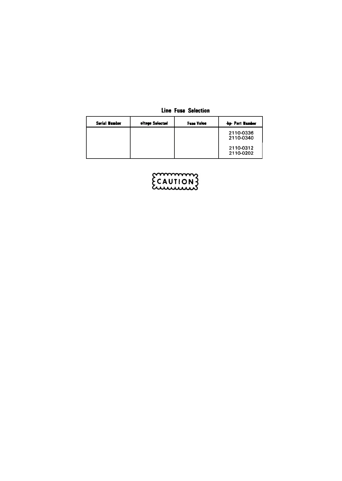
3 . Make sure
that
the line fuse is compatible
with
the
voltage selected.
Table
1.
Une
Fuse
Selection
s.mt
....
v
__
s.IectIlI
Faa
v.1ae
.Part
.....
less
than
100/
120V
O.SA SLO BLOW
2110-0336
2141AOO200
220/240V
OAA
SLO BLOW
2110-0340
2141 AOO200
100f120V
1
.0A
SLO BLOW
2110-0312
and
greater
220/240V
0
.5A
SLO BLOW
2110-0202
Using the
wrong
fuse value
or
fuse
type
will
not
protect
the
circuitry
inside
the
3314A
and
may
result
in damage to
your
3314A.
4.
Connect
the
power
cord. Please
contact
your
local -hp- Sales
Office
if
you
have any questions.
5. Set
the
LINE
switch
to
the
ON position. This
switch
is located in
the
upper
left
hand corner
of
the
front
panel. The
following
actions
will
occur:
-a 2 second
count
down
to
allow electrical stabilization and
test
the
front
panel LEOs
-a CAL ALL to generate a full complement of calibration
constants
-if
the
calibration failed,
the
appropriate error number
will
be displayed
for
1/2
second and the
3314A
will
try
to calibrate
itself
for
another
20
seconds or until a calibration is successful
6.
Connect
the
3314A
to an oscilloscope as
shown
in Figure 1 and
verify
that
the
3314A's
output
is a 1kHz,
10mVp-p
sinewave. Press the FUNCTION
key
to
cycle the
3314A's
function
to squarewave, triangle,
off
and back
to
sinewave. The FUNCTION key is located in
the
lower
right hand corner of
the
front
panel.
More detailed installation procedures are located in Section
2
of
the
Service
Manual.
4

 Loading...


