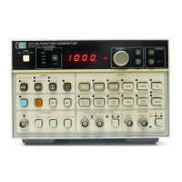
,. '
OUTPUTS
The
3314A
has
the
following
outputs:
-Main Signal
Output
-SYNC
Output
-Trigger
Output
(active
when
Trigger is internal)
-X Axis/Phase
Output
-Z
Axis
Output
-X3
Output
(Option
001)
All
of
the
connectors
are
of
the BNC
type
. The shields are connected
to
the
3314A's
chassis and
protective
earth terminal.
Main Signal
Output
This
fully
protected
output
has a characteristic
output
impedance
of
500.
This
output
must
be
terminated
with
a
500
load before the displayed amplitude is cor-
rect
and before
the
specifications apply. Operation
into
>
500
is allowed
with
a
proportional increase in amplitude and
offset.
Operation
into
<
500
is allowed
with
a
proportional
decrease in amplitude and
offset.
When operating
into
other
than
500,
expect
the
performance
to
decrease, especially at higher frequencies because
of
transmission
line mis-matches.
Outpvt
Overfoad
"£51".The
3314A
disconnects itself from the output connector and displays
E51
for
two
reasons:
- The
output
voltage exceeds safe operating limits
of
± 15V peak. The
output
voltage
is limited
to
± 1
5V
peak before clipping occurs.
- An external voltage greater than
± 1
5V
peak is applied
to
the
3314A
output.
The
3314A
reconnects
itself
when
the
error condition is corrected.
SYNC
Output
This
fully
protected
output
has a characteristic
output
impedance
of
-
500
when
terminated
into
s
500.
When
terminated
into
>
500,
it
will
deliver
TTL
compatible
levels (OV
to
> 2.
5V).
The
maximum
unloaded voltage is
limited
to
-
3V.
The
SYNC
output
will
disconnect
itself
from
externally applied voltages outside the
range
of
-.5V
to
+
5.5V.
67

 Loading...