EXTERNAL MODULATION
(cant)
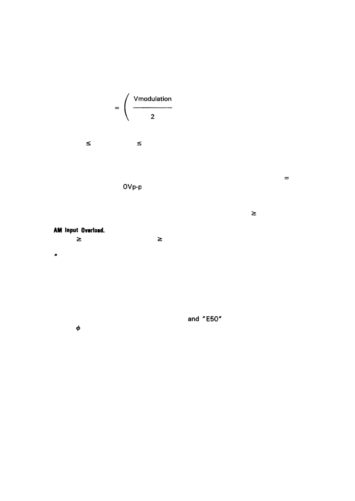
The equation defining
the
relationship
of
instantaneous modulation voltage
to
the
envelope amplitude is:
x VcarrierlVp-p}
2
1
-)
+
2
Vmodulation
-(-
VenveJope(Vp-p}
where
Vcarrier =
the
3314A's
displayed amplitude and
-10V
:s Vmodulation :s +
10V
Observations:
-The carrier amplitude is
1/2
the displayed value
when
VmoduJation = OV.
-The
envelope = OVp-p
when
Vmodulation
=
-lV.
-The carrier is
180
0
out
of
phase
when
Venvelope is negative
IVmodulation
is
more negative
than
-1V}.
-The Reduce
Input
light
will
come on
when
modulation is
~
1
00%.
AM
Input
Overload.
The Reduce
Input
light
will
come on whenever
the
AM
modula-
tion is
~
100%.
AM
modulation
~
100%
can be sensed
from
the
HP-IB
when
bit
#1
of
the
Status
Byte is unmasked. The Reduce Input
light's
HP-IB equivalent is
"
ER50".
Envelope distortion occurs
when
the
output
'clips at approximately
10%
over
the
maximum
amplitude allowed in each amplitude range. Note: Amplitude
modulation >
100%
will
not
necessarily
distort
the
AM envelope. The
AM
envelope is
distorted
when
distortion
sidebands are present,
not
when
the ratio
of
total sideband
power
to
carrier
power
is greater than 1. A synchronous AM detec-
tor
is required
to
recover
the
modulating signal undistorted. Note
that
a non-
synchronous
detector
such as a peak
detector,
cannot recover
the
modulating
signal,
undistorted.
The Reduce Input
light
and'"
E50"
are inhibited
while
in either
of
the
tP
Lock modes
when
the
phase locked loop is unlocked.
57