Section
TII
Model
333A/334A
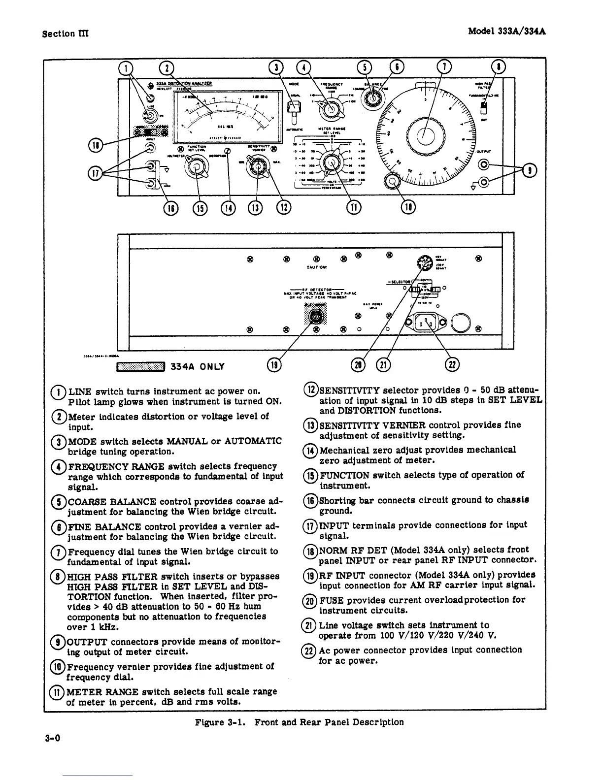
@LINE switch turns instrument ac power on.
Pilot lamp glows when instrument
is
turned
ON.
@Meter indicates distortion
or
voltage level of
input.
@MODE switch selects MAIUUAL
or
AUTOMATIC
bridge tuning operation.
@FREQUENCY RANGE switch selects frequency
range which corresponds
to
fundamental of input
@COARSE BALANCE control provides coarse
ad-
justment for balancing the
Wien
bridge circuit.
6
FINE BALANCE control provides
a
vernier
ad-
'justment for balancing the Wien bridge circuit.
7
Frequency
dial
tunes
the
Wien
bridge
circuit to
'fundamental
of
input signal.
@HJGH PASS FILTER switch inserts
or
bypasses
HIGH
PASS
FILTER
in
SET LEVEL and
DIS-
TORTION function. When inserted, filter pro-
vides
>
40
dB attenuation
to
50
-
60
Hz hum
components but no attenuation
to
frequencies
over
1
kHz.
@OUTPUT
connectors provide means of monitor-
ing output of meter circuit.
@Frequency vernier provides
fine
adjustment of
frequency dial.
@METER RANGE switch selects
full
scale range
of meter
in
percent,
dB
and rms volts.
Signal.
OSENSITMTY selector provides
r)
-
50
dB
atteau-
@SENSITIVITY VERNIER control provides fine
@Mechanical zero adjust provides mechanical
OFUNCTION switch selects type of operation
of
@Shorting
bar
connects circuit ground
to
chassis
@INPUT terminals provide connections for input
ation of input signal
in
10
dB
steps
in
SET LEVEL
and
DISTORTION functions.
adjustment of sensitivity setting.
zero adjustment of meter.
instrument.
ground.
stgnal.
@RF
INPUT
connector (Model
334A
only) provides
input connection for
AM
RF carrier input signal.
20
FUSE provides current overload protection for
0
instrument circuits.
21
Line voltage switch sets inrrtrument to
'operate
from
100
V/120
V/220
V/240
V.
@)
Ac power connector provides input connectton
for ac power.
~~~
Figure
3-1.
Front and Rear Panel Description
3-
0