Model
333AI334A
SECTION
VI1
CIRCUIT DIAGRAMS
Section
M
diagrams
as
well
as
component location drawings
of
each
printed
circuit
board.
7-1.
INTRODUCTION.
7-2*
This
section
cOntahlS
circuit
diagrams
to
aid
in
7-3.
Genera schematic notes, which apply to
dl
the
the operation and maintenance of the Models
333A
and
334A.
Figure
7-1
is
an
internal wiring diagram
that
shows
the
colors
of
the
circuit board wires.
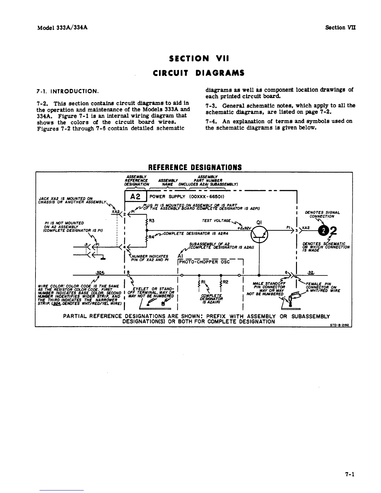
7-4. An
explanation
of
terms and symbols used
on
Figures 7-2 through
7-6
contain detailed schematic
schematic
diagrams,
the schematic diagrams
is
given below.
listed
on
page
7-2.
REFER EN CE DESIGN
AT1
0
NS
ASSEMBLY
ASSEMELY
REFERENCE
ASSEMEL7
PART NUYEER
DEUWATION NAME WXJDES A241 SWASSEMELYI
-
---
------
DENOTES SIGNAL
TEST
VOLTAGE
JACK XA2
IS
HOUNTED
ON
CHASSIS OR ANOTHER ASSEMBLY
COMPLETE DESIGNATOR
IS
A2R4
SUBASMBLY
Of
A2
(COMPLETE DESIGNATOR
IS
A2611
I
-
I
I
18
FEMALE PIN
I-
WIRE
COLOR:
COLOR
COOE
IS
THE SAME
I
1s
THE RESISTOR COLOR CODE
FIRST
WMEER INDICATES EASE
COlbR
SECOND
I
OFF
TERMINAL MAY OR
UlJBER INDENTIFIES WIDER STdlP, AND MAY NOT
BE
NbMEER€D
WE THIRD INDICATES THE NARROWER
STRIP.
(&&
DENOTES WtiT/RED/TZL WIRE)
OR
STIIND-
1
YPLETE
SMNLITOR
2
IS
AZAIRI
PARTIAL REFERENCE DESIGNATIONS ARE SHOWN: PREFIX WITH ASSEMBLY OR SUBASSEMBLY
STO-8-2192
DESIGNATION(S) OR BOTH FOR COMPLETE DESIGNATION
7-1